PRS-D4100F/XU/UC
16
1
2
3
4
1
2
3
4
C
D
F
A
B
E
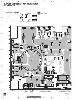
4. PCB CONNECTION DIAGRAM
4.1 AMP PCB
A
A
AMP PCB
Capacitor
Connector
P.C.Board
Chip Part
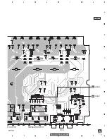
SIDE B
SIDE A
NOTE FOR PCB DIAGRAMS
1.The parts mounted on this PCB
include all necessary parts for
several destination.
For further information for
respective destinations, be sure
to check with the schematic dia-
gram.
2.Viewpoint of PCB diagrams
FRONT
BFC
FUSE
FUSE
SPEAKER OUTPUT
POWER TERMINAL
Summary of Contents for Premier PRS-D4100F
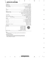
Page 5: ...PRS D4100F XU UC 5 5 6 7 8 5 6 7 8 C D F A B E 1 SPECIFICATIONS ...
Page 18: ...PRS D4100F XU UC 18 1 2 3 4 1 2 3 4 C D F A B E A A AMP PCB ...
Page 19: ...PRS D4100F XU UC 19 5 6 7 8 5 6 7 8 C D F A B E A SIDE B ...
Page 30: ...PRS D4100F XU UC 30 1 2 3 4 1 2 3 4 C D F A B E 7 1 2 CONNECTOR FUNCTION DESCRIPTION ...
Page 34: ...PRS D4100F XU UC 34 1 2 3 4 1 2 3 4 C D F A B E 8 OPERATIONS ...
Page 35: ...PRS D4100F XU UC 35 5 6 7 8 5 6 7 8 C D F A B E ...


