32
HTP-072
1
2
3
4
A
B
C
D
E
F
1
2
3
4
2. Disassembly
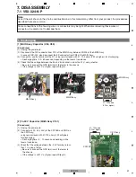
[1] Front Panel Section
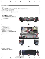
Remove the cabinet by removing the 10 screws.
(1) Remove the five screws.
(BBZ30P080FTB)
(2) Remove the two screws.
(BBZ30P080FTC)
(3) Remove the two screws.
(1500001206010-IL)
(4) Cut the three binders.
(5) Release the two jumper wires.
(6) Disconnect the one flexible cable and three
connectors.
(C
N
704B, CP5, CP701, CP2006)
(7) Unhook the two hooks.
(8) Remove the front panel section.
1
1
1
1
1
2
2
6
6
6
6
4
5
4
4
8
7
7
3
3
• Bottom view
Front panel section
CPU Assy
G-L Assy
STBY Assy
D-MAI
N
Assy
Note:
For performing the diagnosis shown below, the following jigs for service is required:
• 10P extension jig cable (GGD1628)
• 3P extension jig cable (GGD1773)
• Board to board extension jig cable (GGD1849)
• Board to board extension jig cable (GGD1850)
• Board to board extension jig cable (GGD1851)
CP701
CP2006
CP5
C
N
704B
Summary of Contents for HTP-072
Page 9: ...9 HTP 072 5 6 7 8 5 6 7 8 A B C D E F ...
Page 73: ...73 HTP 072 5 6 7 8 5 6 7 8 A B C D E F ...
Page 80: ...80 HTP 072 1 2 3 4 A B C D E F 1 2 3 4 C SIDE B CP2001 CP2000 Q2043 Q2041 IC2018 Q2038 ...
Page 81: ...81 HTP 072 5 6 7 8 5 6 7 8 A B C D E F C C D MAIN ASSY SIDE B CP2003 CP2006 CP2005 CP2200 ...


