17
5
6
7
8
F
E
D
C
B
A
5
6
7
8
GM-X572/XR/UC
1
Fig.1
-
Removing the Amp Unit (Fig.1)
Remove the eight screws.
1. Remove the eight screws and then remove the Case.
-
Removing the Case (not shown)
3
4
4
4
2
1
Amp Unit
2
Remove the screw and then remove
the two Panels.
3
Remove the eight screws and then
remove the two Heat Sinks.
4
Remove the five screws and then
remove the Amp Unit.
Panel
1
1
1
1
1
1
1
Panel
Heat Sink
Heat Sink
3
3
3
3
3
3
3
4
4
7. GENERAL INFORMATION
7.1 DIAGNOSIS
7.1.1 DISASSEMBLY
6. ADJUSTMENT
There is no information to be shown in this chapter.
Summary of Contents for GM-X572/XR/ES
Page 4: ...4 1 2 3 4 1 2 3 4 F E D C B A GM X572 XR UC 2 EXPLODED VIEWS AND PARTS LIST 2 1 PACKING ...
Page 6: ...6 1 2 3 4 1 2 3 4 F E D C B A GM X572 XR UC 2 2 EXTERIOR ...
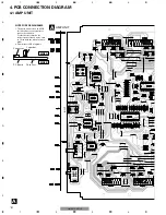
Page 12: ...12 1 2 3 4 1 2 3 4 F E D C B A GM X572 XR UC A A AMP UNIT 1 1 1 ...
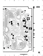
Page 13: ...13 5 6 7 8 F E D C B A 5 6 7 8 GM X572 XR UC A SIDE B ...
Page 18: ...18 1 2 3 4 1 2 3 4 F E D C B A GM X572 XR UC 7 1 2 CONNECTOR FUNCTION DESCRIPTION ...


