background image

GM-X422, GM-X322

The speak

er output mode can be tw

o-chan-

nel (stereo),

one-channel (mono),

or three-

channel ( mono). 

T

o

 connect the

speak

er leads to suit the mode. Connect the

speak

ers according to f

igures on the fol-

lo

wing pages.

When connecting to the speak

er input,

do not

connect the RCA output.

When connecting to the RCA input,

do not

connect the speak

er input.

T

wo-channel mode (stereo)

One-channel mode (mono)

Three-channel mode ( mono)

The po

wer amplif

ier is basically a tw

o-

channel/one-channel bridgeable amplif

ier

,

b

ut three channels can be achie

v

ed by

combining the stereo and mono modes

using inductors and capacitors.

Thr

ee-channel mode,

tw

o-way system

Thr

ee-channel mode,

thr

ee-way system

The inductor (L1 or L2 in the diagram)

acts as a lo

w-pass f

ilter

The capacitor

(C1 or C2 in the diagram) acts as a high-

pass f

ilter

The inductor (L)

shall be used

on the w

oofer/sub-w

oofer

,

and that a

capacitor (C) shall be used on the

high/mid-high.

Remember when bridging an amplif

ier it

will see only half of the original speak

er

impedance. Therefore,

you 

must 

use

speak

ers that ha

v

e ratings of 4 ohms or

higher

. If you use speak

ers that ha

v

e

lo

wer impedance ratings it may cause

damage to the amplif

ier

.

When the inductors and capacitors are

connected to the speak

er wires,

secure or

solder them so the

y cannot be pulled

loose. 

T

ape or use heat shrink on the

joints to pre

v

ent short circuits.

C2

C2

L1

L2

L2

C1

C1

C1

L1

(Right)

Speak

er input

(Left)

(Left)

Speak

er

(Right)

(Right)

Speak

er input

(Left)

Speak

er

(Mono)

Mid-high (Left)

W

oofer (Mono)

Mid-high (Right)

High/mid-high

(Left)

Mid/mid-bass

(Left)

W

oofer/sub-w

oofer

(Mono)

Mid/mid-bass

(Right)

High/mid-high

(Right)

19

-

CONNECTING THE SPEAKER WIRES

(1) GM-X422/X1R/UC, GM-X322/X1R/UC

The speak

er output mode can be tw

o-channel (stereo),

one-channel (mono).

T

o

 connect the speak

er leads to suit the mode. Connect the speak

ers

according to f

igures on the follo

wing pages.

When connecting to the speak

er input,

do not connect the RCA output.

When connecting to the RCA input,

do not connect the speak

er input.

T

wo-channel mode (stereo)

One-channel mode (mono)

(Right)

Speak

er input 

(Left)

(Left)

Speak

er

(Right)

(Right)

Speak

er input

(Left)

Speak

er

(Mono)

(2) GM-X422/X1R/ES

The speaker output mode can be two-channel (stereo), one-channel

(mono). To connect the speaker leads to suit the mode. Connect the speak-

ers according to figures on the following pages.

Two-channel mode (stereo) 

One-channel mode (mono)

(Left)

Speaker

(Right)

Speaker

(Mono)

(3) GM-X422/X1R/EW

Fig. 18

Fig. 19

Fig. 20

Fig. 21

Fig. 22

Fig. 23

Fig. 24

Fig. 25

Summary of Contents for GM-X322

Page 1: ...ety and reliability of the product and may void the warranty If you are not qualified to perform the repair of this product properly and safely you should mot risk trying to do so and refer the repair to a qualified service technician UC model CAUTION This service manual is intended for qualified service technicians it is not meant for the casual do it yourselfer Qualified technicians have the nec...

Page 2: ... 8 Cord Assy See Contrast table 2 9 1 Owner s Manual See Contrast table 2 9 2 Owner s Manual See Contrast table 2 9 3 Warranty Card HRY1070 9 4 Caution Card See Contrast table 2 9 5 Card See Contrast table 2 1 PACKING SECTION PARTS LIST Mark No Description Part No Mark No Description Part No NOTE Parts marked by are generally unavailable because they are not in our Master Spare Parts List Screws a...

Page 3: ...3 HKC0003 8 Cord Assy Not used HDE4419 HDE4419 Not used 9 1 Owner s Manual HRD0048 HRD0045 HRD0047 HRD0046 9 2 Owner s Manual Not used HRD0049 Not used Not used 9 3 Warranty Card HRY1070 Not used HRY1087 Not used 9 4 Caution Card HRP0006 Not used Not used Not used 9 5 Card Not used Not used Not used ARY1048 Owner s Manual Model Part No Language GM X422 X1R UC HRD0048 English French GM X422 X1R ES ...

Page 4: ...4 GM X422 GM X322 2 2 EXTERIOR Fig 2 ...

Page 5: ...Diode D907 ESAC25M 02C 39 Diode D910 ESAC25M 02N 40 System Remote Control See Contrast table 2 41 Badge Unit See Contrast table 2 42 Light Pipe Unit HXA0182 43 Special Red Battery Wire See Contrast table 2 1 EXTERIOR SECTION PARTS LIST Mark No Description Part No Mark No Description Part No 2 CONTRAST TABLE GM X422 X1R UC GM X422 X1R ES GM X422 X1R EW and GM X322 X1R UC are constructed the same ex...

Page 6: ...ARTS LIST MOTHER PCB A ISOLATOR PCB B UC and ES models only C851 852 UC ES 100P EW 470P R469 R470 22k 22k R469 470 GM X322 only VR452 GM X422 only 10 50 10 50 4R7 50 4R7 50 SPEAKER INPUT LEVEL LPF HPF BASS BOOST 15 REGULATOR 15 REGULATOR SWITCHING REGULATOR THERMO DETECTION MUTE L R R L AMP UNIT Consists of MOTHER PCB ISOLATOR PCB AUDIO SIGNAL SIGNAL ROUTE A B ...

Page 7: ...EW models only ES and EW models only 22 50 MUTE BUFFER AMP PRE DRIVER POWER AMP OVER CURRENT DETECTOR OVER VOLTAGE PROTECTOR SWITCHING CONTROL POWER CONTROL MUTE OVER CURRENT DETECTOR HEK0015 15A GROUND WIRE BATTERY WIRE SYSTEM REMOTE CONTROL Fig 3 A ...

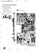
Page 8: ...ER PCB Capacitor Connector P C Board Chip Part SIDE A SIDE B NOTE FOR PCB DIAGRAMS 1 The parts mounted on this PCB include all necessary parts for several destination For further information for respective destinations be sure to check with the schematic dia gram 2 Viewpoint of PCB diagrams ...

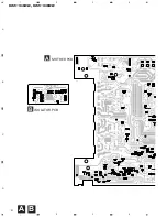
Page 9: ...9 GM X422 GM X322 5 6 7 8 A B C D 5 6 7 8 Fig 4 B A SIDE A OUT IN B ISOLATOR PCB ...

Page 10: ...10 GM X422 GM X322 A 1 2 3 4 B C D 1 2 3 4 A B B ISOLATOR PCB A MOTHER PCB ...

Page 11: ...11 GM X422 GM X322 5 6 7 8 A B C D 5 6 7 8 Fig 5 A SIDE B ...

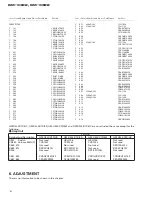
Page 12: ...Diode HZS7L B2 D 655 Diode 1SS133 D 656 Diode HZS7L A2 D 657 Diode 1SS133 D 658 Diode 1SS133 D 901 LED BR4361F D 902 Diode ERA15 02VH D 903 Diode ERA15 02VH D 904 Diode HZS18L 3 D 905 Diode 1SS133 D 906 Diode 1SS133 D 907 Diode ESAC25M 02C D 908 Diode HZS16L 1 D 909 Diode HZS16L 1 D 910 Diode ESAC25M 02N D 911 Diode 1SS133 L 851 Ferri Inductor CTF1007 L 852 Ferri Inductor CTF1007 L 901 Choke Coil ...

Page 13: ...57 RS1 10S104J R 658 RS1 10S472J R 659 RS1 10S103J R 660 RD1 4PU222J R 661 RS1 10S472J R 662 RD1 4PU221J R 663 RS1 10S103J R 664 RD1 4PU473J R 665 RD1 4PU103J R 666 RD1 4PU103J R 667 RD1 4PU222J R 668 RD1 4PU472J R 669 RD1 4PU101J R 670 RS1 10S104J R 671 RS1 10S221J R 672 RD1 4PU152J R 673 RD1 4PU472J R 674 RS1 10S472J R 676 RD1 4PU222J R 678 RS1 10S103J R 680 RS1 10S223J R 681 RS1 10S223J R 682 R...

Page 14: ...YB472K50 C 857 CCSQCH470J50 C 858 CCSQCH470J50 C 859 CCSQCH470J50 C 860 CCSQCH470J50 C 861 CEAS100M50 C 862 CEAS100M50 C 863 CKSQYB103K50 C 864 CKSQYB103K50 C 901 CEAS1R0M50 C 902 CEAS221M10 C 903 CEAS2R2M50 C 904 CEAS1R0M50 C 905 CQMA472J50 C 906 CQMA472J50 C 907 3300µF 16V CCH1130 C 908 3300µF 35V CCH1200 C 909 3300µF 35V CCH1200 C 910 CEAS101M35 C 911 CEAS101M35 C 912 CEAS100M50 C 913 CEAS100M5...

Page 15: ...Heat sink and the Sub Heat Sink therefore to remove the Amp Unit from the Heat Sink 1 Remove four screws B and Three screws C 2 Use 2 pcs of screw B and insert them into the two holes marked with an arrow 3 Alternately tighten them little by little until the Sub Heat Sink separates from the Heat Sink Removing the Case and Panel 1 Remove six screws A and then remove case 2 Remove panel Fig 6 Fig 7 ...

Page 16: ...ck of the power amplifier clockwise If the sound dis torts when the volume is turned up turn the gain control counter clockwise Set the gain control to NORMAL when this amplifier is connected to a Pioneer car stereo with RCA output jacks If the sound is too low or distorts adjust the gain con trol Power Indicator The power indicator lights when the power is switched on Bass Boost Level Control Bas...

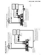
Page 17: ...trol terminal connect the male terminal to the power terminal through the ignition switch CONNECTION DIAGRAM 1 GM X422 X1R UC Fuse 30 A Grommet RCA input Special red battery wire After making all other connections at the amplifier connect the battery wire terminal of the amplifier to the positive terminal of the battery Ground wire black Connect to metal body or chassis Amplifier with RCA input ja...

Page 18: ...ct to the vehicle body 1 Pass the battery wire from the engine compartment to the interior of the vehicle After making all other connections to the amplifier connect the battery wire terminal of the amplifier to the positive terminal of the battery 2 Connect the wires to the terminal Fix the wires securely with the terminal screws 1 Expose the end of the speaker wires by about 10 mm and twist it u...

Page 19: ...ance ratings it may cause damage to the amplifier When the inductors and capacitors are connected to the speaker wires secure or solder them so they cannot be pulled loose Tape or use heat shrink on the joints to prevent short circuits C2 C2 L1 L2 L2 C1 C1 C1 L1 Right Speaker input Left Left Speaker Right Right Speaker input Left Speaker Mono Mid high Left Woofer Mono Mid high Right High mid high ...

Page 20: ...on 4 8 Ω allowable Frequency response 10 50 000 Hz 0 dB 1 dB Signal to noise ratio UC and ES models 105 dB IHF A network Signal to noise ratio EW model 105 dB IEC A network Distortion 0 004 10 W 1 kHz Separation 60 dB 1 kHz Low pass filter Cut off frequency 80 Hz Cut off slope 18 dB oct High pass filter Cut off frequency 80 Hz Cut off slope 12 dB oct Bass boost GM X422 Frequency 40 120 Hz Gain 0 1...

Reviews: