8
GM-D9705/XEVEL
1
2
3
4
A
B
C
D
E
F
1
2
3
4
2
3
1
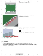
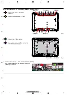
Remove 9 pcs screw and remove
BRACKET.
Remove a Thermistor with the bond.
4
Remove 4 pcs PCB supporter.
Remove 8 pcs screw and then remove the
P.C.B TOTAL ASSY(MAIN).
Fig. 4
Fig. 5
3
1
1
1
1
1
1
3
3
4
4
4
4
4
4
4
4
-
Removing the P.C.B TOTAL ASSY(MAIN) (Fig. 4 and Fig. 5)
3
1
1
1
BRACKET
BRACKET
_
Caution of Re-installation of the P.C.B TOTAL ASSY(MAIN)
When the heatsink will be set, take care not to pinch
the wire of Thermistor.
P.C.B TOTAL ASSY(MAIN)
BRACKET
BRACKET
Thermistor


