background image

2

GM-1006ZG

2. EXPLODED VIEWS AND PARTS LIST

2.1 EXTERIOR

1. SAFETY INFORMATION

This service manual is intended for qualified service technicians; it is not meant for the casual do-it-yourselfer.
Qualified technicians have the necessary test equipment and tools, and have been trained to properly and safely repair
complex products such as those covered by this manual.
Improperly performed repairs can adversely affect the safety and reliability of the product and may void the warranty.
If you are not qualified to perform the repair of this product properly and safely; you should not risk trying to do so
and refer the repair to a qualified service technician.

Summary of Contents for GM-1006ZG

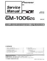
Page 1: ...n ORDER NO CRT2522 AMPLIFIER GM 1006ZG X1H UC Service Manual GM CONTENTS 1 SAFETY INFORMATION 2 2 EXPLODED VIEWS AND PARTS LIST 2 3 SCHEMATIC DIAGRAM 4 4 PCB CONNECTION DIAGRAM 10 5 ELECTRICAL PARTS LIST 14 6 ADJUSTMENT 17 7 GENERAL INFORMATION 18 7 1 DIAGNOSIS 18 7 1 1 DISASSEMBLY 18 7 1 2 CONNECTOR FUNCTION DESCRIPTION 19 8 SPECIFICATIONS 19 3 1 2 6 4 5 9 7 8 10 11 12 A B 3 1 2 6 4 5 9 7 8 10 11...

Page 2: ...ssary test equipment and tools and have been trained to properly and safely repair complex products such as those covered by this manual Improperly performed repairs can adversely affect the safety and reliability of the product and may void the warranty If you are not qualified to perform the repair of this product properly and safely you should not risk trying to do so and refer the repair to a ...

Page 3: ...roduct are used for disassembly EXTERIOR SECTION PARTS LIST Mark No Description Part No 1 Screw BMS30P050FMC 2 Screw BMZ26P200FMC 3 Case HNB0085 4 Heat Sink HNR0107 5 Mother Unit HWM6323 6 Connector CN801 HKE0028 7 Connector CN802 HKE0029 8 Holder HNC0057 9 Screw PPZ40P080SAD 10 Chassis Unit HXA0281 11 IC IC701 702 TDA7384 12 IC IC703 PAL005A ...

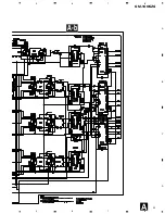
Page 4: ...1006ZG A 1 2 3 4 B C D 1 2 3 4 A a A b A a A a A b A b A b A b A a A a Large size SCH diagram Guide page Detailed page 3 SCHEMATIC DIAGRAM 3 1 OVERALL CONNECTION DIAGRAM GUIDE PAGE Note When ordering service parts be sure to refer to EXPLODED VIEWS AND PARTS LIST or ELECTRICAL PARTS LIST A a A ...

Page 5: ...5 GM 1006ZG 5 6 7 8 A B C D 5 6 7 8 A b A ...

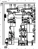
Page 6: ...6 GM 1006ZG A 1 2 3 4 B C D 1 2 3 4 A MOTHER UNIT 3 1 2 6 4 5 9 7 8 10 11 12 A B 3 1 2 6 4 5 9 7 8 10 11 12 A a A a A b 1 2 3 ...

Page 7: ...7 GM 1006ZG 5 6 7 8 A B C D 5 6 7 8 B A C D E F G H A a A a A b 5 4 6 7 8 9 ...

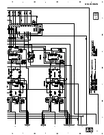
Page 8: ...8 GM 1006ZG A 1 2 3 4 B C D 1 2 3 4 A a A b A b 1 2 3 ...

Page 9: ...9 GM 1006ZG 5 6 7 8 A B C D 5 6 7 8 A a A b A b 5 4 6 7 8 9 ...

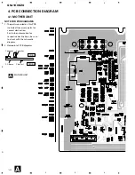
Page 10: ...TE FOR PCB DIAGRAMS 1 The parts mounted on this PCB include all necessary parts for several destination For further information for respective destinations be sure to check with the schematic diagram 2 Viewpoint of PCB diagrams Capacitor Connector P C Board Chip Part SIDE A SIDE B A A H D E A ...

Page 11: ...11 GM 1006ZG 5 6 7 8 A B C D 5 6 7 8 B1 A1 B12 A12 SIDE A A ...

Page 12: ...12 GM 1006ZG A 1 2 3 4 B C D 1 2 3 4 A MOTHER UNIT A ...

Page 13: ...13 GM 1006ZG 5 6 7 8 A B C D 5 6 7 8 SIDE B A ...

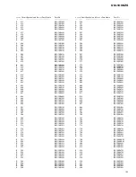
Page 14: ...p components Chip Resistor RS1 _S___J RS1 __S___J Chip Capacitor except for CQS CKS CCS CSZS Unit Number HWM6323 Unit Name Mother Unit MISCELLANEOUS IC 101 IC NJM2068MD IC 102 IC NJM2068MD IC 201 IC NJM2068MD IC 202 IC BA3308F IC 203 IC NJM2068MD IC 304 IC BA3308F IC 401 IC NJM2068MD IC 402 IC NJM2068MD IC 501 IC NJM2068MD IC 502 IC NJM2068MD IC 503 IC BA3308F IC 601 IC NJM2068MD IC 602 IC NJM2068...

Page 15: ...4 RS1 10S102J R 547 RS1 10S753J R 548 RS1 10S753J R 549 RS1 10S122J R 550 RS1 10S122J R 551 RS1 10S332J R 552 RS1 10S332J R 553 RS1 10S152J R 554 RS1 10S152J R 557 RS1 10S753J R 558 RS1 10S753J R 559 RS1 10S122J R 560 RS1 10S122J R 561 RS1 10S332J R 562 RS1 10S332J R 563 RS1 10S512J R 564 RS1 10S512J R 565 RS1 10S472J R 566 RS1 10S472J R 567 RS1 10S102J R 568 RS1 10S102J R 569 RS1 10S820J R 570 RS...

Page 16: ...01 CKSYB274K16 C 502 CKSYB274K16 C 503 CKSYB104K50 C 504 CKSYB104K50 C 505 CKSYB184K25 C 506 CKSYB184K25 C 507 CKSYB153K50 C 508 CKSYB153K50 C 509 CKSQYB563K50 C 510 CKSQYB563K50 C 511 CKSQYB273K50 C 512 CKSQYB273K50 C 513 CKSQYB683K16 C 514 CKSQYB683K16 C 515 CKSQYB332K50 C 516 CKSQYB332K50 C 517 CKSQYB153K50 C 518 CKSQYB153K50 C 519 CKSQYB391K50 C 520 CKSQYB391K50 C 521 CCSQCH121J50 C 522 CCSQCH...

Page 17: ...0M50 C 901 CCSQCH101J50 C 902 CCSQCH101J50 C 903 CCSQCH101J50 C 904 CCSQCH101J50 C 905 CCSQCH101J50 C 906 CCSQCH101J50 C 907 CCSQCH101J50 C 908 CCSQCH101J50 C 909 CCSQCH101J50 C 910 CCSQCH101J50 C 911 CCSQCH101J50 C 912 CCSQCH101J50 C 921 CCSQCH101J50 C 922 CCSQCH101J50 C 923 CCSQCH101J50 C 924 CCSQCH101J50 6 ADJUSTMENT There is no information to be shown in this chapter ...

Page 18: ...7 1 DIAGNOSIS 7 1 1 DISASSEMBLY Removing the Mother Unit Remove the ten screws and then remove the Heat Sink Fig 1 Remove the five screws and then remove the Mother Unit Fig 2 Fig 1 Fig 2 Heat Sink Mother Unit Removing the Case not shown ...

Page 19: ...nt In B6 Right Front In B7 Left Front In B8 Left Front In B9 Front Door R B10 Front Door R B11 Front Door L B12 Front Door L A B AMPSENSE C D E RSA F AMP Enable G POWER B H GND Power source 14 4 V DC 9 3 16 0 V allowable Grounding system Negative type Dimensions 188 W 46 H 175 9 D mm Rated power output 18 W or more at 14 4 V 1k Hz 3 THD Front Rear ERS 35 W or more at 14 4 V 80 Hz 3 THD Subwoofer L...

Reviews: