Pioneer DV-360-K Service Manual Download Page 8


DV-360-S

8

1

2

3

4

1

2

3

4

C

D

F

A

B

E


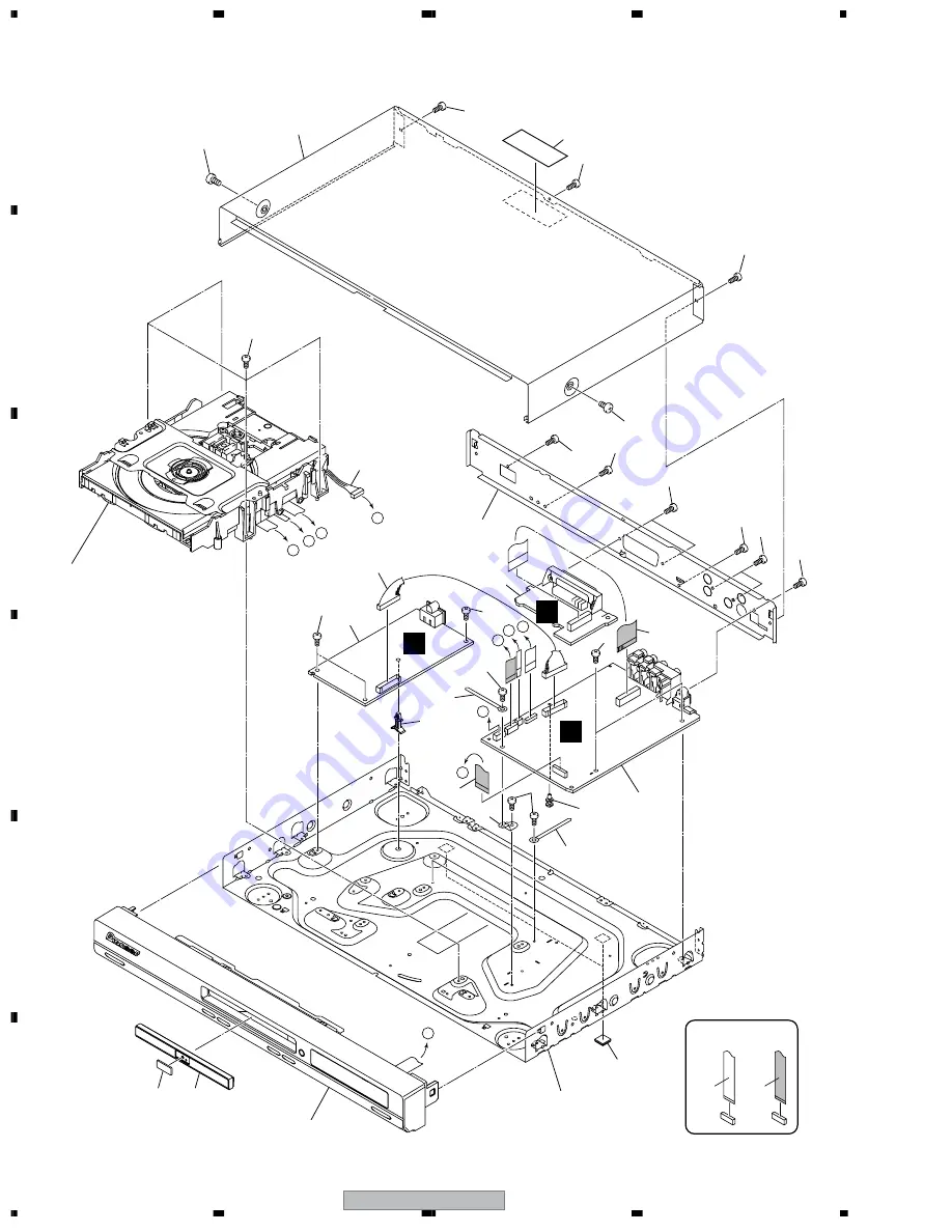
2.2  EXTERIOR SECTION

CONTACT SIDE

NON-CONTACT 

  SIDE

14

9

8

8

18

18

18

12

20

19

18

13

10

5

4

6

3

2

7

1

11

15

Refer to
"2.3 FRONT PANEL SECTION".

Refer to
"2.4 LOADING MECHA. ASSY".

B

E

F

18

19

22

19

19

19

19

20

17

17

16

19

19

21

B

C D

E

B

C

D

E

A

A

23

Summary of Contents for DV-360-K

Page 1: ...pore 159936 PIONEER CORPORATION 2003 DV 360 S RRV2738 DVD PLAYER DV 360 S DV 360 K THIS MANUAL IS APPLICABLE TO THE FOLLOWING MODEL S AND TYPE S Model Type Power Requirement Region No Serial No Please confirm 3rd 4th alphabetical letters DV 360 S WYXCN AC220 240V 2 TE DV 360 S WYXCN FG AC220 240V 2 TE DV 360 S WVXCN AC220 240V 2 TE DV 360 K WYXCN AC220 240V 2 TE DV 360 K WYXCN FG AC220 240V 2 TE F...

Page 2: ...PUT POWER 5 mW WAVELENGTH 780 nm Additional Laser Caution See page 49 1 Laser Interlock Mechanism Loading switch S101 on the LOAB Assy is used for interlock mechanism of the laser When this switch turned ON in SW2 CLOSE side OPEN signal is 0V and CLOSE signal is 3 5V a laser becomes the status which can completely oscillation Furthermore the laser completely oscillates in the disc judgment and dis...

Page 3: ...s 5 Lubricants glues and replacement parts Appropriately applying grease or glue can maintain the product performances But improper lubrication or applying glue may lead to failures or troubles in the product By following the instructions in this manual be sure to apply the prescribed grease or glue to proper portions by the appropriate amount For replacement parts or tools the prescribed ones sho...

Page 4: ...ASSY 35 4 2 DVDM ASSY 36 4 3 FLKY ASSY 40 4 4 IRKY ASSY 41 4 5 POWER SUPPLY UNIT VWR1366 42 4 6 POWER SUPPLY UNIT VWR1368 43 4 7 SCRB ASSY 44 5 PCB PARTS LIST 45 6 ADJUSTMENT 47 6 1 ADJUSTMENT ITEMS AND LOCATION 47 6 2 JIGS AND MEASURING INSTRUMENTS 47 6 3 NECESSARY ADJUSTMENT POINTS 48 6 4 TEST MODE 49 6 5 MECHANISM ADJUSTMENT 50 7 GENERAL INFORMATION 53 7 1 DIAGNOSIS 53 7 1 1 TEST MODE 53 7 1 2 ...

Page 5: ...CA jack Audio output 1 stereo pair Output level During audio output 200 mVrms 1 kHz 20 dB Number of channels 2 Jack RCA jack Digital audio characteristics Frequency response 4 Hz to 44 kHz DVD fs 96 kHz S N ratio 115 dB Dynamic range 101 dB Total harmonic distortion 0 0016 Wow and flutter Limit of measurement 0 001 W PEAK or lower Digital output Optical digital output Optical digital jack Coaxial ...

Page 6: ...of the safety factor of the part Therefore when replacing be sure to use parts of identical designation Screws adjacent to mark on product are used for disassembly For the applying amount of lubricants or glue follow the instructions in this manual In the case of no amount instructions apply as you think it appropriate NOTES WVXCN Type Only WYXCN and WYXCN FG Types Only 15 14 12 16 3 4 6 9 Operati...

Page 7: ...2 Sheet VHL1006 13 Pad L VHA1338 14 Pad R VHA1339 15 Packing Case See Contrast table 2 16 Polyethylene Bag See Contrast table 2 17 Accessory Box See Contrast table 2 Mark No Description Part No Mark No Symbol and Description DV 360 S WYXCN DV 360 S WYXCN FG DV 360 S WVXCN DV 360 K WYXCN DV 360 K WYXCN FG 1 Power Cable ADG1154 ADG1154 ADG1156 ADG1154 ADG1154 6 Operating Instructions Not used Not us...

Page 8: ... 2 EXTERIOR SECTION CONTACT SIDE NON CONTACT SIDE 14 9 8 8 18 18 18 12 20 19 18 13 10 5 4 6 3 2 7 1 11 15 Refer to 2 3 FRONT PANEL SECTION Refer to 2 4 LOADING MECHA ASSY B E F 18 19 22 19 19 19 19 20 17 17 16 19 19 21 B C D E B C D E A A 23 ...

Page 9: ...rast table 2 13 PCB Base VNE2279 14 DVD V Plate See Contrast table 2 15 Tray Panel See Contrast table 2 16 Bonnet Case S See Contrast table 2 17 Screw See Contrast table 2 18 Screw BBZ30P060FMC 19 Screw BBZ30P080FZK 20 Screw PPZ30P080FMC NSP 21 SCRB Assy VWV1934 22 Flexible Cable 20P VDA1950 23 Label VRW1872 Mark No Description Part No Mark No Symbol and Description DV 360 S WYXCN DV 360 S WYXCN F...

Page 10: ...DV 360 S 10 1 2 3 4 1 2 3 4 C D F A B E 2 3 FRONT PANEL SECTION CONTACT SIDE NON CONTACT SIDE D C 6 7 5 3 1 8 8 4 2 8 8 8 8 ...

Page 11: ... IRKY Assy VWG2415 3 Connector Assy 4P VKP2298 4 FP Angle VNE2297 5 Rubber Foot VEB1349 6 Front Panel Assy See Contrast table 2 7 Pioneer Name Plate See Contrast table 2 8 Screw PPZ30P080FMC Mark No Description Part No Mark No Symbol and Description DV 360 S WYXCN DV 360 S WYXCN FG DV 360 S WVXCN DV 360 K WYXCN DV 360 K WYXCN FG 6 Front Panel Assy VXA2607 VXA2607 VXA2607 VXA2605 VXA2605 7 Pioneer ...

Page 12: ...il GYA1001 Mark No Description Part No NSP 1 LOAB Assy VWG2426 2 Traverse Mecha Assy S VXX2871 3 Loading Motor Assy VXX2872 4 Motor Pulley PNW1634 5 Motor VXM1105 6 Flexible Cable 24P VDA1945 7 Connector Assy 2P VKP2253 8 Floating Rubber VEB1351 9 Belt VEB1330 10 Stabilizer VNE2253 11 Loading Base VNL1917 12 Float Base DVD VNL1918 13 Drive Cam VNL1919 14 Gear Pulley VNL1921 15 Loading Gear VNL1922...

Page 13: ...View Daifree GEM1036 Inner side of a ditch Concave of unevenness Top View Bottom View Daifree GEM1036 Daifree GEM1036 Side of the rib Lubricating Oil GYA1001 Concave of unevenness Daifree GEM1036 Concave of unevenness Daifree GEM1036 Lubricating Oil GYA1001 Lubricating Oil GYA1001 Lubricating Oil GYA1001 Inner side of a ditch Lubricating Oil GYA1001 Inner side of a ditch Lubricating Oil GYA1001 ...

Page 14: ...tor To DVDM CN102 Spindle Motor To DVDM CN101 Pickup Assy CONTACT SIDE NON CONTACT SIDE 3 7 8 1 17 16 12 17 10 13 17 10 6 11 14 16 2 9 15 Torque 0 15 0 01 N m 15 Torque 0 15 0 01 N m 4 Adjustment screw 5 Adjustment spring Screw Tight GYL1001 Silicone Adhesive GEM1037 Silicone Adhesive GEM1037 ...

Page 15: ...1101 3 Pickup Assy S OXX8005 4 Skew Screw VBA1080 5 Skew Spring VBH1335 6 Guide Bar VLL1514 7 Sub Guide Bar VLL1515 8 Leaf Spring VNC1023 9 Joint Spring VNC1019 10 Support Spring VNC1020 NSP 11 Mecha Chassis VNE2248 12 Damper Sheet VEB1335 13 Spacer VNL1913 14 Joint 03 VNL1949 15 Tapping Screw OBA8016 16 Screw BBZ20P050FZK 17 Screw PMA26P100FMC ...

Page 16: ...1 22 23 24 18 9 16 9 10 3 4 A C 17 19 8 6 CN101 24P CN1013 CN102 12P CN401 13P CN101 CN2 13P LOAD SW2 V 3D LOAD M S101 2 1 1 2 3 4 1 2 SW1 V 3D 5 5 3 4 CN103 24P CN601 13 12 11 8 7 V S_C S_Y G Y B Cb R Cr D OUT 36 LO 37 LO H1 H1 H2 H2 H3 H3 CN602 5 3 2 6 CN104 5 4 2 13 12 11 8 7 5 4 2 28V FL DC FL DC EV 3 3V CN105 15P 4 6 2 5 SW 1 8V EV 6V A EV 6V B SW 12V AC IN CN1 E POWER SUPPLY UNIT LIVE NEUTRA...

Page 17: ...0P JA401 EURO CONNECTOR CN801 20P 15 19 13 11 9 5 3 1 6 8 10 12 16 18 20 V V Y R C AUD L OUT G B H L 15 3 AUD R OUT 1 11 7 Y C AUDIO_L 7 14 AUDIO_R G Y B Cb R Cr IC401 MM1505XN 6 4 2 L H D IRKY ASSY IC101 PE5374A FL CONTROL MICROCOMPUTER CN101 15P 12 10 14 11 4 4 28V KEY1 KEY3 KEY0 SEL IR V 3E 60 17 22 KEY 20 21 FL101 FL TUBE C FLKY ASSY X101 5MHz 4 3 X1 X2 IR102 Remote Sensor Unit RPM7240 H4 CN10...

Page 18: ...iv 2 IC301 pin 36 FG V 1V div H 5msec div 15 IC301 pin 55 LOAD_DRV V 1V div H 500nsec div 5 Foot of R656 IC701 pin 3 AUDIO DAC LRCK 6 Foot of R656 IC701 pin 3 AUDIO DAC LRCK 7 Foot of R651 IC701 pin 1 AUDIO DAC BCK 8 Foot of R652 IC701 pin 2 AUDIO DAC DATA Waveform of DATA is unsettled V 2V div H 5µsec div 6 7 8 10 IC801 pin 20 Video out G V 1V div H 10µsec div 11 IC801 pin 18 Video out B V 2V div...

Page 19: ...DV 360 S 19 5 6 7 8 5 6 7 8 C D F A B E ...

Page 20: ... D F A B E 3 3 LOAB ASSY and OVERALL WIRING DIAGRAM POWER SUPPLY UNIT VWR1366 or VWR1368 E DVDM ASSY VWS1556 B SCRB ASSY VWV1934 F Note When ordering service parts be sure to refer to EXPLODED VIEWS and PARTS LIST or PCB PARTS LIST ...

Page 21: ...Y VWG2408 C IRKY ASSY VWG2415 D PICKUP ASSY S OXX8005 SPINDLE MOTOR VXM1099 STEPPING MOTOR VXM1101 LOADING MOTOR ASSY VXX2872 LOAB ASSY VWG2426 A F T T F F F T T F F S S S S FOCUS SERVO LOOP LINE TRACKING SERVO LOOP LINE F T STEPPING SERVO LOOP LINE S ...

Page 22: ...DV 360 S 22 1 2 3 4 1 2 3 4 C D F A B E 3 4 DVDM ASSY 1 3 FRONT END BLOCK B 1 3 S S S S F F T T F F T T F F S S S S B 1 3 DVDM ASSY VWS1556 CN601 STEPPING MOTOR SPINDLE MOTOR PICKUP ASSY S A 17 ...

Page 23: ...DV 360 S 23 5 6 7 8 5 6 7 8 C D F A B E B 1 3 F F F F T T FOCUS SERVO LOOP LINE TRACKING SERVO LOOP LINE STEPPING SERVO LOOP LINE F T S 2 3 B 15 16 2 1 1 2 Refer to 3 2 WAVEFORMS ...

Page 24: ...DV 360 S 24 1 2 3 4 1 2 3 4 C D F A B E 3 5 DVDM ASSY 2 3 BACK END BLOCK B 2 3 VYW2061 S Y Y S C C V B Cb G Y R Cr D B 2 3 DVDM ASSY VWS1556 1 3 B 3 3 B 3 3 B 3 3 B 3 3 B 1 3 B 3 3 B 3 3 B ...

Page 25: ...5 15 15 15 15 15 R Cr G Y B Cb V S C C S Y Y S C C S Y Y R Cr G Y B Cb V V SIGNAL ROUTE S VIDEO OUT C C SIGNAL ROUTE S VIDEO OUT Y Y SIGNAL ROUTE R Cr SIGNAL ROUTE G Y SIGNAL ROUTE B Cb SIGNAL ROUTE AUDIO SIGNAL ROUTE D AUDIO DIGITAL SIGNAL ROUTE VWR1366 CN101 VWR1368 CN2 E CN101 C 3 3 B 3 3 B ...

Page 26: ... 1 2 3 4 C D F A B E 3 6 DVDM ASSY 3 3 AUDIO VIDEO BLOCK B 3 3 2 2K 1 5K MM1623AF S C C V S Y Y G Y B Cb R Cr S C C V S Y Y B Cb R Cr G Y B 3 3 DVDM ASSY VWS1556 2 3 B 2 3 B 2 3 B 2 3 B AUDIO DAC VIDEO DRIVER 3 7 4 6 5 8 ...

Page 27: ...C D D S C C V S Y Y B Cb R Cr G Y S C C S Y Y V G Y S C C S Y Y V B Cb R Cr S C C S Y Y R Cr G Y B Cb V V SIGNAL ROUTE S VIDEO OUT C C SIGNAL ROUTE S VIDEO OUT Y Y SIGNAL ROUTE R Cr SIGNAL ROUTE G Y SIGNAL ROUTE B Cb SIGNAL ROUTE AUDIO SIGNAL ROUTE D AUDIO DIGITAL SIGNAL ROUTE 2 3 B 2 3 B CN402 F 9 10 11 12 13 14 3 Refer to 3 2 WAVEFORMS ...

Page 28: ...DV 360 S 28 1 2 3 4 1 2 3 4 C D F A B E 3 7 FLKY and IRKY ASSYS C FLKY ASSY VWG2408 C ...

Page 29: ...DV 360 S 29 5 6 7 8 5 6 7 8 C D F A B E C D The power supply is shown with the marked box IRKY ASSY VWG2415 D CN105 B2 3 FLKY ASSY S105 7 S106 8 S107 0 S108 3 IRKY ASSY S101 STANDBY ON S103 4 1 S104 ...

Page 30: ...WER SUPPLY SYPS Unit is repaired Please take care to keep the space not touching other parts when replacing the parts POWER SUPPLY UNIT VWR1366 E CAUTION FOR CONTINUED PROTECTION AGAINST RISK OF FIRE REPLACE ONLY WITH SAME TYPE NO 491 800 MFD BY LITTELFUSE INC FOR P301 AEK7063 CAUTION FOR CONTINUED PROTECTION AGAINST RISK OF FIRE REPLACE ONLY WITH SAME TYPE NO 49101 6 MFD BY LITTELFUSE INC FOR P10...

Page 31: ...it is repaired Please take care to keep the space not touching other parts when replacing the parts POWER SUPPLY UNIT VWR1368 E CP4 AEK7012 1 6A CAUTION FOR CONTINUED PROTECTION AGAINST RISK OF FIRE REPLACE ONLY WITH SAME TYPE NO 491 800 MFD BY LITTELFUSE INC FOR CP1 AEK7008 CAUTION FOR CONTINUED PROTECTION AGAINST RISK OF FIRE REPLACE ONLY WITH SAME TYPE NO 49101 6 MFD BY LITTELFUSE INC FOR CP4 A...

Page 32: ...DV 360 S 32 1 2 3 4 1 2 3 4 C D F A B E 3 10 SCRB ASSY F G Y S C C S Y Y V S Y Y V B Cb R Cr S C C R Cr SCRB ASSY VWV1934 F CN801 B3 3 ...

Page 33: ... The power supply is shown with the marked box V Y R C R C G B V Y G B S C C S Y Y R Cr G Y B Cb V V SIGNAL ROUTE S VIDEO OUT C C SIGNAL ROUTE S VIDEO OUT Y Y SIGNAL ROUTE R Cr SIGNAL ROUTE G Y SIGNAL ROUTE B Cb SIGNAL ROUTE AUDIO SIGNAL ROUTE ...

Page 34: ...DV 360 S 34 1 2 3 4 1 2 3 4 C D F A B E ...

Page 35: ...matic diagrams 2 A comparison between the main parts of PCB and schematic diagrams is shown below 3 The parts mounted on this PCB include all necessary parts for several destinations For further information for respective destinations be sure to check with the schematic diagram 4 View point of PCB diagrams Symbol In PCB Diagrams Symbol In Schematic Diagrams Part Name B C E D D G G S S B C E B C E ...

Page 36: ... R615 R624 R695 R694 R690 R675 R610 R612 R613 R626 IC604 C620 CN401 C626 C628 C627 C629 C602 L602 R408 C690 Q401 R441 R443 R442 Q402 R444 Q403 R657 C607 C619 C622 C624 R631 C636 C641 C659 C684 R614 R627 R625 R403 R402 C420 C422 C406 R405 R406 C413 C C404 C405 C403 CN105 IC400 R400 R411 R689 R688 Q603 R450 R239 R234 C415 R409 C134 R300 C136 C421 C409 R345 R440 C407 C130 R240 Q405 R445 C433 Q404 IC4...

Page 37: ...R861 R851 C863 C853 L851 L861 C862 C861 R841 C843 C852 C842 C805 C851 C841 C833 R831 C832 D803 D804 D802 C831 C804 C823 R821 C822 D801 C802 C821 C811 C813 R811 C812 R801 C803 C801 R802 Q801 R796 Q803 Q802 C793 C792 Q791 R795 R794 R791 R793 Q804 R792 C791 JA701 R758 R728 Q758 R718 R748 Q748 C713 IC801 R812 CN801 R805 JA801 R71 R622 R807 C411 R413 R707 C615 R7210 R7230 R7110 R7130 L797 D730 R797 Q73...

Page 38: ...DV 360 S 38 1 2 3 4 1 2 3 4 C D F A B E SIDE B B 1 7 10 20 1 23 CN CN801 CN802 C DVDM ASSY B VNP1902 A CN801 ...

Page 39: ...DV 360 S 39 5 6 7 8 5 6 7 8 C D F A B E SIDE B B 1 12 1 4 1 5 1 15 CN103 CN102 CN104 CN101 23 24 2 CN401 13 CN105 CN401 CN101 CN104 CN102 CN103 CN105 ...

Page 40: ...3 1 XREADY VWG2412 14 FLDC 15 GND 13 GND 12 VFDP 11 V 3E 10 FLDC 8 RESET 6 SCK 7 CTS 9 ACK 4 S M TO F 3 POWER ON 2 S F TO M 5 XRESET 1 5 2 1 4 0 4 1 6 0 6 1 8 0 1 2 0 1 15 CN102 CN103 CN101 W107 X101 W113 S106 S105 W101 FL102 W102 S109 S107 FL101 W103 C101 CN102 W124 W108 W110 W126 W112 W114 W115 W111 IR102 W120 W116 S115 S116 S114 S112 S110 S113 S118 W119 W122 S117 L102 W117 W121 W118 C188 S111 S...

Page 41: ...182 D107 D106 R192 C186 R153 VWG2415 VWG2416 IRKY ASSY VWG2414 1 5 KEY LED V 3E IR GND CN104 CN105 D105 C181 CN104 W125 IR101 S101 W128 L101 W127 S103 S104 W130 VWG GNDV VWG2416 KPC 1694V 0 3 3V IRKY ASSY VWG2414 VWG2415 POWERON CN105 1 5 BACKWARD FORWARD PC CN102 C CN104 CN104 IRKY ASSY D VNP1906 A ...

Page 42: ...DV 360 S 42 1 2 3 4 1 2 3 4 C D F A B E 4 5 POWER SUPPLY UNIT VWR1366 SIDE A SIDE B E E P101 P301 CN401 B AC IN CN101 CN1 CN1 VWR1366 POWER SUPPLY UNIT E ...

Page 43: ...DV 360 S 43 5 6 7 8 5 6 7 8 C D F A B E 4 6 POWER SUPPLY UNIT VWR1368 SIDE A SIDE A E E CP4 CP1 CN401 B AC IN CN2 CN1 VWR1368 POWER SUPPLY UNIT E ...

Page 44: ... SCRB ASSY 11 C 9 AUDIO_L 13 Y 17 VSEL2 15 V 3 B CB CN101 20P 19 VSEL1 1 R CR 7 AUDIO_R 5 G Y 2 GNDV 6 GNDV 20 V 12V 1 6 3 4 1 6 3 4 1 20 1 2 21 20 CN402 W406 W407 W410 W402 W403 W401 W404 W405 C413 C417 C421 CN402 JA401 W408 W409 C403 C404 C422 17 VSEL2 3 B CB 13 Y 1 R CR 15 V 5 G Y 6 GNDV 8 GNDA 10 GNDV V 5V 14 GNDV CN101 20P 16 SQUEEZE V 12V 2 GNDV 12 GNDV 4 GNDV SCRB ASSY NC V 5V GNDV VWV1934 ...

Page 45: ...1 M63018FP IC401 MM1565AF IC801 MM1623AF IC703 NJM78L05UA IC701 PCM1742KE IC402 IC403 PQ1L333M2SP IC400 PST3228 IC601 STM5589CVA IC301 STM6316ATXXA IC604 TC7WU04FU IC603 VYW2061 Q390 Q753 2SA1576A Q401 Q403 2SA1602A Q202 Q212 Q402 Q730 Q791 2SC4081 Q746 Q748 Q756 Q758 2SD2114K Q666 DTC114TUA Q751 Q752 DTC114YUA Q201 Q211 HN1A01F Q603 RN4982 D730 1SS355 D603 RB501V 40 COILS AND FILTERS L707 LAU4R7J...

Page 46: ...05 S108 ASG7013 CAPACITORS C183 CKSRYB102K50 C102 C105 C187 CKSRYF104Z25 C104 CKSRYF104Z50 RESISTORS All Resistors RS1 16S J OTHERS CN102 CONNECTOR B4B PH K IC104 REMOTE RECEIVER RPM7240 H4 V101 FLUORESCENT TUBE VAW1077 CN101 15P CONNECTOR VKN1275 X101 5MHz VSS1142 DIRKY ASSY VWG2415 SWITCHES AND RELAYS S101 S103 S104 ASG7013 RESISTORS All Resistors RS1 16S J Mark No Description Part No OTHERS CN1...

Page 47: ...ectrical Part Tangential and Radial Height Coarse Adjustment DVD Jitter Adjustment Initialize the Focus Sweep Setting Electrical adjustments are not required Adjustment Points Mechanism Part Cautions After adjustment adjustment screw locks with the Screw tight Screwdriver large TV monitor Precise screwdriver DVD test disc GGV1025 Test mode remote control unit GGF1067 Screw tight GYL1001 Screwdrive...

Page 48: ... the following step finally when replaced Pickup Traverse Mechanism and Spindle Motor Purpose To set the sweep which was correct with the individual Traverse mechanism Mechanical point Electric point LOAB and DVDM ASSYS GGF1067 Test mode remote control unit ESC CLEAR Exchange Parts of Mechanism Assy Exchange PCB Assy When Adjustment Points Exchange the Pickup Exchange the Traverse Mechanism Exchan...

Page 49: ...TEST MODE OFF An address is displayed For example when playback with 30000 During PLAY Press keys in order OR ESC 030000 PLAY When playback with the target address of disc DVD TV LDP 10 3 0 0 0 0 CHP TIM ESC TEST CHECK DVD CD CAUTION Perform only trace video and audio outputs are nothing The TEST MODE functions that are used only during adjustment are described here For details see 7 1 1 TEST MODE...

Page 50: ...it at need This parts is Traverse mechanism exclusive use of a model for 2003 years Put a spacer between a Tangential or Radial adjustment screw and Mechanism Base and turn each screw to adjust the height Refer to 6 1 ADJUSTMENT ITEMS AND LOCATION START Tangential and Radial Height Coarse Adjustment 1 Loading Mecha Assy 7 3mm Turn a flat side into bottom Spacer for Height adjustment Float Base Not...

Page 51: ...t jitter becomes minimum Use disc GGV1025 START DVD Jitter Adjustment 2 J J Min J Min Test mode end J Min ESC Disc playback normally The measurement of block error rate If error rate is OK locks a root of tangential and radial adjustment screws with the Screw tight and go to step Screw tight GYL1001 Turn the POWER OFF in case of NG once and perform the adjustment once again Confirm the error rate ...

Page 52: ...B E Initialize the Focus Sweep Setting 3 Turn on the Player ESC CLEAR POWER Note Be sure to perform this step when replaced the Pickup or Traverse mechanism Purpose To set the sweep which was correct with the individual Traverse mechanism ...

Page 53: ...ssing the TEST A8 5E and 2 A8 02 keys in order 2 Repeat focus sweep by pressing the TEST A8 5E and 3 A8 03 keys in order 7 Spindle FG servo CAV Press the TEST A8 5E and 5 A8 05 keys in order then rise up the spindle and FG servo becomes on CLV Press the TEST A8 5E and 9 A8 09 keys in order then rise up the spindle and FG servo becomes on 8 Tracking open close 1 Open tracking by pressing the STEP F...

Page 54: ...ecimal In the address input mode turn to the hexadecimal input by pressing the PROGRAM A8 4C key display a mark and 1 to 6 keys are each input as A to F Hexadecimal input and decimal input can switch with toggle In case of CD perform only the absolute time search 3 Search execution Press the CHP TM A8 13 key of the remote control unit After the search perform only trace and video and audio outputs...

Page 55: ...Switch ON 01 In Side Switch OFF 00 9 Output video system V NTSC system NTSC PAL system PAL Automatic setting AUTO Scart terminal output SK Display only the WY model which can do the output setting of scart terminal VIDEO 00 S VIDEO 01 RGB 02 0 Disc sensing DSC The type of discs loaded is displayed DVD CD VCD Jitter value J Version of the AV 1 chip version of firmware AV Version of the FL controlle...

Page 56: ... an error message is displayed and the tray opens Command Contents Conditions Remote Control Key Name Remote Control Code Memory clear and resion revision indication CLEAR 1 A8 45 Average value measurement of DVD error rate 5 1 A8 05 CD error rate measurement 5 1 A8 05 Aspect Pan scan 2 AF A2 Aspect Letter box 3 AF A3 Aspect Wide 4 AF A4 Digital AC3 5 AF A5 Digital AC 3 PCM 6 AF A6 Virtual surroun...

Page 57: ...roller 3 Region No 4 Part number 5 ROM version 6 Flash size 7 FL controller version 8 CHIP VERSION Version of ST CHIP CUT ID JTAG ID two columns eight columns 9 B E VERSION Version of BACK END version of ST core software softwareVersion softwareRevision buildNumber 0 F E VERSION Version of FRONT END version of mechanism controller CHIP software MainVersion Kinds of firmware RAM or ROM Remote contr...

Page 58: ...E added 2 byte EDC data F E error 4 Self diagnosis functions Whether F E is normal or not is checked FE OK No abnormality in F E FE Error Abnormality is recognized in F E Pressing the CHP TIM key again displays the mechanical error history Each press of the CHP TIM key changes the displays between the mechanical error history and the Service Mode display For details on the mechanical error history...

Page 59: ...ut 0x11 Focus off error 0x02 Focus off timeout 0x12 Focus lost error 0x03 Focus lost timeout 0x13 Focus balance adjust error 0x04 Focus balance adjust timeout 0x14 Focus gain adjust error 0x05 Focus gain adjust timeout 0x15 Focus sweep error 0x06 Focus sweep timeout 0x16 Focus reflection error 0x07 Focus reflection timeout 0x17 TRACKING ERROR 0x2 TRACKING TIMEOUT 0x3 Tracking on error 0x21 Trackin...

Page 60: ...ance adjust error 0 x 24 ATB could not be completed 1 Pickup Tracking gain adjust error 0 x 25 AGC could not be completed 1 Pickup Tracking jump error 0 x 26 Tracking jump could not be completed TRACKING TIMEOUT 0 x 3 Tracking on timeout 0 x 31 Did timeout at tracking on Are not there a dirt or a scratch in the Disc 1 Pickup 2 Driver 3 Front End IC Tracking off timeout 0 x 32 Did timeout at tracki...

Page 61: ...otating Is FG output from the driver Is the PDM output from Front End 1 Spindle motor 2 Spindle driver 3 Front End IC Spindle CLV timeout 0 x 75 Did timeout at CLV on ACQUISITION ERROR 0 x 8 PLL lost error 0 x 83 PLL is lost Are not there a dirt or a scratch in the Disc 1 Pickup 2 Front End IC ACQUISITION TIMEOUT 0 x 9 PLL lost timeout 0 x 93 Did timeout at PLL backup Are not there a dirt or a scr...

Page 62: ...ers Compare mode Enter the same ID number again Only if your two input numbers match the ID number is set Compare mode helps eliminate mistyping of the ID number 4 After entering all 9 digits if you press the SEARCH key the unit unconditionally sets the input number as the ID number Then the unit automatically enters Player s Data Input Mode The SEARCH key is not accepted after all 9 digits have b...

Page 63: ...ally deletes the ID number and exits this mode If the numbers do not match the disc tray is opened and the unit exits this mode The STOP key is not accepted after all 9 digits have been entered 6 Player s ID Number Setting ID Number 0 0 0 0 0 0 0 0 1 Compare CLEAR Exit Input ID Number 3 2 4 Player s ID Number Setting ID Number 0 0 0 0 0 0 0 0 1 Compare 0 0 0 0 0 0 0 0 1 OK PLAY Enter STOP Memory C...

Page 64: ...ot start reading the data In this case open then close the tray 3 To exit this mode press the CLEAR key While data are being read from the ID DISC GGV1085 you cannot exit this mode 4 Player s ID Number Setting ID Number 0 0 0 0 0 0 0 0 1 Compare CLEAR Exit STEREO ID Data Setting Mode Input ID Number 2 Player s Data Input Mode CLEAR Exit Insert The ID Data Disc 4 Player s Data Input Mode Rom Write ...

Page 65: ...RESET L H BACK END Accesses flash ROM and 64M SDRAM BACK END Accesses FRON END FL controller Request communication to BACK END FP_XRDY BACK END Outputs the communicable signal to FL controller FP_ACK BACK END FL controller communication The opening picture appears FRONT END Check the following Slider positioning INSIDE SW Spindle FG stop Disc detection Focus control Spindle turn Read ID informatio...

Page 66: ...ower cannot be on Diagnosis of the DVDM Assy 2 6 3 3 5 5 4 Tray Panel Tray Slit Tray open Drive Gear Loading Mecha Assy Screwdriver small Screwdriver small Projection Insert a screwdriver small into the slit located at the bottom of the unit and slide the projection of the Drive Gear in the Loading Mecha Assy in the direction of the arrow as indicated in the photo If the Tray pops out a little ful...

Page 67: ...six hooks 2 Remove the front panel section Front Panel Section 2 1 Remove the four screws 2 Remove the three screws 3 Remove the DVDM Assy and stand it against the other parts DVDM Assy 3 Front panel section 2 1 1 1 1 1 1 2 3 1 1 1 DVDM Assy DVDM Assy 2 3 ...

Page 68: ...ment connect the flexible cable then remove the soldered joint open 5 Remove the four screws that secure the Loading Mecha Assy to the unit Loading Mecha Assy 1 Rear View Front Side 1 3 1 1 2 2 1 2 2 Loading Base Triangle Drive Cam Pin Hook Bridge Tray Note when reinserting the Tray C D Removing the Traverse Mecha Assy S and Pickup Assy S When reinserting the Tray first align the triangle printed ...

Page 69: ...om their factory placement 2 Remove the four hooks 3 Remove the Traverse Mecha Assy S Traverse Mecha Assy S 2 2 Bottom View Traverse Mecha Assy S Flexible cable for the pickup Flexible cable for the spindle motor 1 1 1 2 2 2 3 Flexible cable for the stepping motor Front Side ...

Page 70: ...justment screws and two adjustment springs 4 Remove the Pickup Assy S Pickup Assy S 3 Note The Pickup Assy S can be removed without removing the Traverse Mecha Assy S shown as Step ø Bottom View Flexible cable for the pickup 1 4 3 3 1 2 Front Side Pickup Assy S Adjustment screw Skew screw Adjustment screw Skew screw Adjustment spring Skew spring Adjustment spring Skew spring ...

Page 71: ... Note The screws are secured with epoxy Make sure to apply epoxy after reattaching the screws Leaf Spring Joint Spring Joint 03 Conductive surface Hook Hook Arrangement of the flexible cable for the spindle motor Conductive surface Arrangement of the flexible cable for the stepping motor Front Side Front Side Bottom View Bottom View ...

Page 72: ...ing inward 7 Pass the flexible cable below the hook and fold it back 8 Fold the flexible cable back at the hook 9 Fold the flexible cable along the hook 4 Pass the flexible cable through the hook not allowing any slack 6 Hook the part folded in Step 1 to the hook 5 Fold the flexible cable as indicated in the photo Hook Bottom View 5 6 Make sure there is no slack in the cable Reference line Referen...

Page 73: ...7 2 IC 7 STM6316ATXXA DVDM ASSY IC301 FRONT END IC Block Diagram The information shown in the list is basic information and may not correspond exactly to that shown in the schematic diagrams List of IC STM6316ATXXA STM5589CVA M63108FP PE5374A ...

Page 74: ... o l a n a 0 2 F C t u p n i C m a e b 3 U P 1 2 E A t u p n i A m a e b 3 U P 2 2 S I D L E I H S V A D N G d n g g o l a n a 3 2 C D A 8 1 C C V A 8 V 1 8 V 1 g o l a n a 4 2 C D A D N G A D N G d n g g o l a n a 5 2 C D A D L E I H S V A D N G d n g g o l a n a 6 2 C A D 3 3 C C V A 3 V 3 3 V 3 g o l a n a 7 2 C A D D N G A D N G d n g g o l a n a 8 2 E L D N I P S 2 t s m h o 0 6 5 e v i r d r...

Page 75: ...E _ T U O N E _ R R E _ S R F I A T A D E B 0 6 S S V D D N G d n g l a t i g i d 1 6 K L C _ T U O K L C B _ S R F I A T A D E B 2 6 8 1 D D V D 8 V 1 8 V 1 l a t i g i d 3 6 D I L A V D _ T U O D I L A V D _ S R F I A T A D E B 4 6 A T A D _ T U O A T A D _ S R F I A T A D E B 5 6 C N Y S _ T U O T S B C C E _ S R F I A T A D E B 6 6 5 E P A M D L C S t u p n i d a o l n w o d e n i t u o r E F ...

Page 76: ... g n i v i r d D L m n 0 5 6 0 9 2 D L D L m n 0 8 7 l a n g i s g n i v i r d D L m n 0 8 7 1 9 3 3 A C C V A 3 V 3 3 V 3 l a t i g i d 2 9 L E S W T D N G R V _ D C D C r o f l a n i m r e t n o i t c n u j R V s e d o i d r o t i n o M 3 9 1 D M L 1 D M L D M L l a n i m r e t n o i t c n u j e g a t l o v r o t i n o M 4 9 2 D M L 2 D M L R V _ D V D D V D r o f l a n i m r e t n o i t c n u j...

Page 77: ... r F t u p n i a t a d l a i r e S 7 1 K L C B _ E F N I e c a f r e t n i m a e r t s 6 1 3 6 L d n E t n o r F t u p n i k c o l c l a i r e S 8 1 D I L A V D _ E F N I e c a f r e t n i m a e r t s 6 1 3 6 L d n E t n o r F t u p n i g a l f d i l a v a t a D 9 1 C N Y S _ E F N I e c a f r e t n i m a e r t s 6 1 3 6 L d n E t n o r F t u p n i g a l f e z i n o r h c n y s l a i r e S 0 2 D I...

Page 78: ...n o i t i s o p p m a l c n u c s i d g n i w o h s r o f l a n g i s t u p n I n o i t i s o p p m a l c c s i d e t e l p m o c H 4 4 S N S _ C S I D T U O r e g n a h C c s i D 5 t p e c x e d e t c e n n o c t o n s i t I N I r e g n a h C c s i D 5 y l n O g n i t s i x e c s i d r o f l a n g i s t u p n I g n i t s i x e L 5 4 2 E T U M V R D X T U O d e v r e s e r 6 4 x P T T U O d e v r ...

Page 79: ... A R D S I M S 8 9 1 1 D _ I M S 9 9 2 1 D _ I M S 0 0 1 3 1 D _ I M S 1 0 1 4 1 D _ I M S 2 0 1 5 1 D _ I M S 3 0 1 S S O R C _ K C A R T T U O d e v r e s e r 4 0 1 M C P X _ D S D T U O d e v r e s e r 5 0 1 T S R X _ C A D T U O d e v r e s e r 6 0 1 K L C M C P _ C D A T U O d e v r e s e r 7 0 1 3 V 3 _ D D V y l p p u s r e w o P V 3 3 8 0 1 S S V d n u o r G 9 0 1 T S R T X N I e c a f r e...

Page 80: ... R D S g u b e D t c e l e s r e p p u L 0 3 1 W X R _ D S T U O e t i r W d a e R M A R D S g u b e D d a e r H e t i r w L 1 3 1 T I A W _ U P C N I t u p n i H t i a w U P C 2 3 1 H S A L F _ E C T U O L e l b a n E p i h C y r o m e m h s a l F 3 3 1 2 E C _ U P C T U O d e v r e s e r 4 3 1 1 E C _ U P C T U O d e v r e s e r 5 3 1 S A R X _ D S T U O L S A R M A R D S g u b e D L e l b a n e...

Page 81: ... t s 6 1 3 6 L d n E t n o r F g a l f r o r r E C C E 8 8 1 1 L E S V T U O l a n g i s t u p t u o G N I K N I L B r o t c e n n o c T R A C S O R U E e l b a s i d t u p t u o B G R L e l b a n e t u p t u o B G R H 9 8 1 2 L E S V T U O l a n g i s C R Y V r o t c e n n o c T R A C S O R U E B G C Y t u p t u o B G R V L B G R V t u p t u o B G R V H 0 9 1 T S R _ E F T U O 6 1 3 6 L d n E t n...

Page 82: ...i n U l o r t n o C c i t s o n g a i D 4 0 2 0 S C X _ C A D T U O l o r t n o c l a i r e s C A D o i d u a r o f e l b a n e p i h C e l b a n e L 5 0 2 1 S C X _ C A D T U O d e v r e s e r 6 0 2 K C A _ P F T U O e c a f r e t n i C A D l e n a P t n o r F H t u p t u o e g d e l w o n k c a e k a h s d n a H 7 0 2 K C S _ P F T U O e c a f r e t n i C A D l e n a P t n o r F t u p t u o k c ...

Page 83: ...DV 360 S 83 5 6 7 8 5 6 7 8 C D F A B E 7 M63018FP DVDM ASSY IC101 BTL Driver IC Pin Arrangement Block Diagram ...

Page 84: ...DV 360 S 84 1 2 3 4 1 2 3 4 C D F A B E Pin Function ...

Page 85: ...round Potential for A D Converter 19 KEY3 IN 8 digit model DV 260 263 Key3 Input Analog input for A D converter 20 KEY2 IN Key Input 2 Analog input for A D converter 21 KEY1 IN Key Input 1 Analog input for A D converter 22 KEY0 IN Key Input 0 Analog input for A D converter 23 VSS0 Ground Potential to Ports 24 AVDD Analog Power Reference Voltage Input to A D Converter 3 3 V 25 VDD0 Positive Power S...

Page 86: ... 10 Output 59 VDD2 Positive Power Supply to FIP Controller Driver 3 3 V 60 VLOAD Pull down Resistor Connection of FIP Controller Driver 28V 61 P9 OUT FIP Segment 9 Output 62 P8 OUT FIP Segment 8 Output 63 P7 OUT FIP Segment 7 Output 64 P6 OUT FIP Segment 6 Output 65 P5 OUT FIP Segment 5 Output 66 P4 OUT FIP Segment 4 Output 67 P3 OUT FIP Segment 3 Output 68 P2 OUT FIP Segment 2 Output 69 P1 OUT FI...

Page 87: ...puter may not be playable on this unit This may be caused by a number of possibili ties including but not limited to the type of disc used the type of recording damage dirt or condensation on either the disc or the player s pick up lens See below for notes about particular software and formats CD R RW compatibility This unit will play CD R and CD RW discs recorded in CD Audio or Video CD Super VCD...

Page 88: ...y Microsoft Corporation WMA data can be encoded by using Windows Media Player version 8 or less or Windows Media Player for Windows XP Windows Media and the Windows logo are trademarks or registered trademarks of Microsoft Corporation in the United States and or other countries Compressed audio compatibility This unit will play CD ROM CD R and CD RW discs containing files saved in the MPEG 1 Audio...

Page 89: ... limits only files and folders up to these limits will be play able Files and folders are read displayed in alphabetical order Note that if the file structure is very complex you may not be able to read play all files on the disc Folder and track names excluding the file extension are displayed There are many different recording bit rates available to encode MP3 files This unit was designed to be ...

Page 90: ... F A B E 7 4 CLEANING Before shipping out the product be sure to clean the following positions by using the prescribed cleaning tools Position to be cleaned Cleaning tools Pickup lenses Cleaning liquid GEM1004 Cleaning paper GED 008 ...

Page 91: ... Press to pause playback Press again to restart 6 3 Press to start or resume playback 12 7 Press to stop the disc you can resume play back by pressing 3 play 14 Display 15 4 1 and Press and hold for fast reverse forward scanning Press to jump to the previous next chapter or track 16 This mark indicates compatibility with DVD RW discs recorded on a DVD recorder in Video Recording mode ...

Page 92: ...t these jacks Use the supplied audio video cable when connecting these jacks Match the colors of the jacks and cables for correct stereo sound 3 AV CONNECTOR RGB TV AV AC IN Receiver This is a combined audio and video output for connection to a TV that has a SCART input Connect using a SCART cable The type of video output can be switched to suit your TV 4 VIDEO OUT 5 Connect the supplied powercabl...

Page 93: ...r 4 Lights when 2V SRS TruSurround is selected 5 Lights during multi angle scenes on a DVD disc 6 Lights in any of the repeat play modes 7 REMAIN Indicates that the character display is showing the disc or title chapter track remain time 8 Character display 9 2 D Lights when a Dolby Digital soundtrack is playing 10 TRK Indicates that the character display is showing a CD or Video CD track number 1...

Page 94: ...ys and menus Press ENTER to select an option or execute a command 7 HOME MENU Press to display or exit the on screen display 8 Use for reverse slow motion playback frame reverse and reverse scanning 9 Press to start or resume playback 10 Press to jump to the beginning of the current chapter or track then to previous chapters tracks 11 Press to pause playback press again to restart 12 PLAY MODE Pre...

Page 95: ...works exactly the same as the ENTER button in 6 above 18 MENU Press to display a DVD disc menu or the Disc Navigator if a VR format DVD RW CD Video CD MP3 WMA or JPEG disc is loaded 19 RETURN Press to return to a previous menu screen 20 Use for forward slow motion playback frame advance and forward scanning 21 Press to jump to the next chapter or track 22 Press to stop the disc you can resume play...

Reviews: