background image


DEH-P9600MP/XN/EW

30

1

2

3

4

1

2

3

4

C

D

F

A

B

E

A-a

D-b

D-a

D-a

D-b

1

2

L209

C217

R1

AND

PICKUP UNIT(P10)(SERVICE)

%

#

@

F

F

F

F

F

F

F

F

F

F

S

C

T

F

S

C

T

F

T

T

T

T

T

T

T

T

T

T

F

F

T

T

Summary of Contents for DEH-P9600MP

Page 1: ...lexandra Road 04 01 Singapore 159936 PIONEER CORPORATION 2004 DEH P9600MP XN EW CRT3192 MULTI CD CONTROL DSP HIGH POWER CD MP3 WMA PLAYER WITH RDS TUNER DEH P9600MP XN EW This service manual should be used together with the following manual s Model No Order No Mech Module Remarks CX 3098 CRT3179 S10WMAcode2 CD Mech Module Circuit Description Mech Description Disassembly For details refer to Import...

Page 2: ...red by this manual Improperly performed repairs can adversely affect the safety and reliability of the product and may void the warranty If you are not qualified to perform the repair of this product properly and safely you should not risk trying to do so and refer the repair to a qualified service technician 1 Safety Precautions for those who Service this Unit When checking or adjusting the emitt...

Page 3: ... monitors and other parts requiring cleaning proper cleaning should be performed to restore their performances 5 Lubricants glues and replacement parts Appropriately applying grease or glue can maintain the product performances But improper lubrication or applying glue may lead to failures or troubles in the product By following the instructions in this manual be sure to apply the prescribed greas...

Page 4: ... DIAGRAM 38 4 1 TUNER AMP UNIT 38 4 2 KEYBOARD UNIT OEL 42 4 3 KEYBOARD UNIT LCD 43 4 4 CD MECHANISM MODULE 44 4 5 SWITCH PCB 46 4 6 CONNECTOR PCB 47 5 ELECTRICAL PARTS LIST 48 6 ADJUSTMENT 57 6 1 JIG CONNECTION DIAGRAM 57 6 2 CD ADJUSTMENT 58 6 3 CHECKING THE GRATING AFTER CHANGING THE PICKUP UNIT 60 6 4 ERROR MODE 62 6 5 FREQUENCY CHECK FOR CLOCK 63 6 6 OEL SCREENSAVER STUDIO IKA TO LKD APPLICAT...

Page 5: ...DEH P9600MP XN EW 5 5 6 7 8 5 6 7 8 C D F A B E 1 SPECIFICATIONS ...

Page 6: ...DEH P9600MP XN EW 6 1 2 3 4 1 2 3 4 C D F A B E ...

Page 7: ...DEH P9600MP XN EW 7 5 6 7 8 5 6 7 8 C D F A B E ...

Page 8: ...se they are not in our Master Spare Parts List Screw adjacent to mark on the product are used for disassembly For the applying amount of lobricants or glue follow the instructions in this manual In the case of no amount instructions apply as you think it appropriate 1 2 24 3 5 5 6 7 8 9 10 11 12 14 15 16 17 17 18 18 19 20 22 23 25 26 27 4 21 13 ...

Page 9: ...20P060FZK 7 Polyethylene Bag CEG 127 8 Handle CNC5395 9 Bush CNV3930 10 Polyethylene Bag CEG 158 11 Polyethylene Bag CEG1088 12 Case Assy CXB8574 13 Microphone Assy CPM1054 14 Sub Carton CHA3258 15 Carton CHG5202 16 Contain Box CHL5202 17 Protector CHP2538 18 Protector CHP2539 19 Protector CHP2541 20 Protector CHP2546 21 Remote Control Unit CXC2665 22 Screw Assy CEA4114 23 Screw BMZ50P060FTC 24 Co...

Page 10: ...DEH P9600MP XN EW 10 1 2 3 4 1 2 3 4 C D F A B E 2 2 EXTERIOR 1 ...

Page 11: ...w BMZ26P140FTC 23 Clamper CEF1035 24 Clamper CEF1036 25 Plug CN981 CKM1278 26 Plug CN811 CKS 787 27 Connector CN701 CKS3837 28 Plug CN101 CKS1058 29 Connector CN872 CKS1082 30 Connector CN871 CKS2211 31 Connector CN771 CKS1036 32 Connector CN703 CKS3126 33 Connector CN351 CKM1389 34 Holder CNC5399 35 Holder CNC9711 36 Holder CNC9713 37 Heat Sink CNR1615 38 FM AM Tuner Unit CWE1645 39 Holder CND105...

Page 12: ...DEH P9600MP XN EW 12 1 2 3 4 1 2 3 4 C D F A B E 2 3 EXTERIOR 2 ...

Page 13: ...V6915 36 Grille Unit CXC2452 37 Knob Unit CXC3686 38 Jack CN1902 CKN1016 39 Screw M2x2 CBA1633 40 Screw CBA1561 41 Spring CBH2530 42 Cushion CNM8895 43 Arm CNV6962 44 Guide CNV6968 45 Guide CNV6967 46 Flexible PCB CNP7913 47 Screw ISS26P055FTC 48 Case Unit CXB7968 49 Cover Unit CXC2453 50 Spring CBH2545 51 Cushion CNM8894 52 Panel Unit CXB7953 53 Drive Unit CXC2514 54 Screw BMZ26P040FTC 55 Screw M...

Page 14: ...8 23 59 87 86 5 13 34 5 5 13 44 5 C 52 53 36 4 73 29 51 18 64 76 50 10 72 75 49 77 67 27 78 60 90 48 8 17 46 6 60 11 89 43 70 14 31 65 85 66 85 31 35 14 74 85 1 2 R 94 91 12 33 61 63 21 79 57 58 62 80 13 4 86 I 45 28 7 24 47 P 41 20 40 69 39 30 P 19 56 F E 22 81 15 G 26 4 54 37 55 93 92 10 D 3 1GEM1024 2GEM1045 3GEM1035 1 1 1 1 1 1 1 1 2 2 2 2 1 1 1 1 1 2 2 1 3 ...

Page 15: ... 39 Arm CND1909 40 Lever CND2032 41 Lever CNC9984 42 Sheet CNM8134 43 Collar CNV7798 44 Guide CNV7799 45 Arm CNV7800 46 Rack CNV7199 47 Holder CNV7201 48 Holder CNV7202 49 Arm CNV7203 50 Gear CNV7207 51 Gear CNV7208 52 Gear CNV7209 53 Gear CNV7210 54 Gear CNV7211 55 Gear CNV7212 56 Rack CNV7214 57 Arm CNV7215 58 Arm CNV7216 59 Guide CNV7217 60 Roller CNV7218 61 Gear CNV7219 62 Arm CNV7221 63 Arm C...

Page 16: ...N VDD 8 5 1 7 CN101 11 FM AM TUNER UNIT 21 12 19 20 PD5913 PD5913A Q741 5 VDCONT 1 CD3VON 23 MCKRQ Q742 BU VR321 MIC321 6 4 1 2 3 5 CN811 VD FEJSW1 FOPSW1 FCLSW1 MOTOR2 MOTOR1 IC 811 BA6288FS 3 14 Q812 Q811 BU FLPPW 11 4 5 6 11 66 65 FLPOPN FLPCLS 69 68 67 fclssw fopnsw flpejsw M M951 AUTOMATIC FLAP MOTOR CLOSE OPEN EJECT SWITCH PCB BU OELPW 22 DPDT1 31 KYDT1 32 SWVDD1 40 BU ILMPW2 43 DPDT2 35 KYD...

Page 17: ...WVDD5V2 ILM B2 CN1901 ILM B DPDT KYDT SWVDD5V KEYBOARD UNIT LCD KEYBOARD UNIT OEL Q651 5 RST1 5 RST VDD2 Q911 ACC 5V REGULATOR IC 1805 PD5917A GRILLE µ COM KEY MATRIX IC 1806 PD8122A ROM OEL UNIT IC 1808 TC7WH32FK 1 28 27 DPDT KYDT 5 IC 1802 S 818A33AUC BGN 1 3 3V 12 XOUT XIN 11 X1801 13 IC 1902 PD6340A GRILLE µ COM KEY MATRIX LCD1901 20 18 DPDT KYDT XO XI 22 X1901 23 SW5V 3 IC 1901 TSOP4840SB1 1 ...

Page 18: ...agram Guide page Detailed page Note When ordering service parts be sure to refer to EXPLODED VIEWS AND PARTS LIST or ELECTRICAL PARTS LIST A a A E 1 2 3 4 M M951 AUTOMATIC FLAP CXB8939 S952 CSN1052 CLOSE S951 CSN1051 OPEN S953 CSN1058 EJECT D CN901 CN902 B CN1801 E SWITCH PCB FM AM TUNER UNIT TUNER 26 0dBs FM 30 AM 30 IP BUS 2 2dBs ...

Page 19: ...ymbol indicates a resistor No differentiation is made between chip resistors and discrete resistors NOTE Symbol indicates a capacitor No differentiation is made between chip capacitors and discrete capacitors F A TUNER AMP UNIT REAR R CH SUB WOOFER R CH SUB WOOFER L CH REAR L CH FRONT R CH FRONT L CH BACKUP GND RL RL FL FL B REM ILL ACC TEL CEK1136 10A RR RR FR FR RR RR FR FR FL FL RL RL ACC GND B...

Page 20: ...DEH P9600MP XN EW 20 1 2 3 4 1 2 3 4 C D F A B E A a A b A a A a A b E 1 2 3 M M951 AUTOMATIC FLAP CXB8939 S952 CSN1052 CLOSE S951 CSN1051 OPEN S953 CSN1058 EJECT E SWITCH PCB ...

Page 21: ...DEH P9600MP XN EW 21 5 6 7 8 5 6 7 8 C D F A B E A a A b A a A a A b 4 D CN901 CN902 B CN1801 FM AM TUNER UNIT TUNER 26 0dBs FM 30 AM 30 IP BUS 2 2dBs ...

Page 22: ...he importance of the safety factor of the part Therefore when replacing be sure to use parts of identical designation A TUNER AMP UNIT REAR R CH SUB WOOFER R CH SUB WOOFER L CH REAR L CH FRONT R CH FRONT L CH TUNER 27 3dBs IP BUS 1 73dBs TUNER 4 37dBs IP BUS 7 66dBs CD 7 55dBs TUNER 6 13dBs IP BUS 18 16dBs CD 18 05dBs ...

Page 23: ... 2R2 0 022 R022 Symbol indicates a resistor No differentiation is made between chip resistors and discrete resistors NOTE Symbol indicates a capacitor No differentiation is made between chip capacitors and discrete capacitors F BACKUP GND RL RL FL FL B REM ILL ACC TEL CEK1136 10A RR RR FR FR RR RR FR FR FL FL RL RL ACC GND BACK UP B REM ILL TUNER 21 63dBs IP BUS 33 66dBs CD 33 55dBs ...

Page 24: ...DEH P9600MP XN EW 24 1 2 3 4 1 2 3 4 C D F A B E 3 3 KEYBOARD UNIT OEL B OEL MODULE A CN871 ...

Page 25: ...DEH P9600MP XN EW 25 5 6 7 8 5 6 7 8 C D F A B E B B KEYBOARD UNIT OEL ...

Page 26: ...DEH P9600MP XN EW 26 1 2 3 4 1 2 3 4 C D F A B E 3 4 KEYBOARD UNIT LCD C F A CN872 REMOTE CONTROL SENSOR RESET SOURCE VOLUME TEXT F CONNECTOR PCB ...

Page 27: ...DEH P9600MP XN EW 27 5 6 7 8 5 6 7 8 C D F A B E C C KEYBOARD UNIT LCD OTE CONTROL SOR LCD CONTROLLER T ...

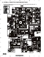
Page 28: ... PAGE D a D L209 C217 R1 AND 4 00MHz M1 CXB6007 SPINDLE MOTOR M2 CXB8933 LOADING CARRIAGE MOTOR PICKUP UNIT P10 SERVICE CD DRIVER 3 3V REGULATOR Pull down 1 2 3 7 8 5 9 0 4 F F F F F F F F F F F F F T S C T T S S C C C C S S S C T F S C T F T T T T T T T T T T F F T T F T S S C C ...

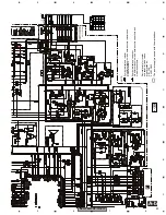
Page 29: ...01 HOME SWITCH ON OFF S902 CLAMP SWITCH ON OFF S903 DSCSNS SWITCH ON OFF S904 12EJ SWITCH ON OFF S905 8EJ SWITCH ON OFF The underlined indicates the switch position A D CN701 CD CORE UNIT S10WMACODE2 MICRO COMPUTER 1 5V REGULATOR 3 3V REGULATOR Pull down A CN703 6 SIGNAL LINE FOCUS SERVO LINE TRACKING SERVO LINE CARRIAGE SERVO LINE SPINDLE SERVO LINE F T C S ...

Page 30: ...DEH P9600MP XN EW 30 1 2 3 4 1 2 3 4 C D F A B E A a D b D a D a D b 1 2 L209 C217 R1 AND PICKUP UNIT P10 SERVICE F F F F F F F F F F S C T F S C T F T T T T T T T T T T F F T T ...

Page 31: ...1 5 6 7 8 5 6 7 8 C D F A B E A a D b D a D a D b 2 3 4 5 4 00MHz M1 CXB6007 SPINDLE MOTOR M2 CXB8933 LOADING CARRIAGE MOTOR CD DRIVER 3 3V REGULATOR Pull down 1 2 3 7 8 5 9 0 4 F F F T S C T T S S C C C C S S F T S S C C ...

Page 32: ... HOME SWITCH ON OFF S902 CLAMP SWITCH ON OFF S903 DSCSNS SWITCH ON OFF S904 12EJ SWITCH ON OFF S905 8EJ SWITCH ON OFF The underlined indicates the switch position D CD CORE UNIT S10WMACODE2 1 5V REGULATOR A CN703 SIGNAL LINE FOCUS SERVO LINE TRACKING SERVO LINE CARRIAGE SERVO LINE SPINDLE SERVO LINE F T C S ...

Page 33: ...DEH P9600MP XN EW 33 5 6 7 8 5 6 7 8 C D F A B E D a D b D b 2 3 4 5 470P C722 1 C906 R22 C910 2R2 PE5423A LRCKOK LRCK BCK DOUT EMPH A CN701 MICRO COMPUTER 3 3V REGULATOR Pull down A CN703 6 ...

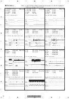
Page 34: ...500mV div 500mV div 500mV div 20ms div Ref REFO Mode Normal TE FE 500mV div 500mV div 200ms div Source On setup operation CD DA Play operation Ref REFO Mode Normal FE 0 FIN TE 9 TIN 500mV div 500mV div 500mV div 500mV div 20ms div CD ROM play operation Regular track Jump Ref REFO Mode Normal MDX 7 SIN 2V div 1V div 5µs div Ref REFO Mode Normal MDX 7 SIN 1V div 200mV div 50ms div Spindle waveform d...

Page 35: ... CIN 9 TIN 1V div 500mV div 500mV div 500ms div Ref REFO Mode Normal 1 DSCSNS 2 8SNS 3 12SNS 4 LOEJ 5V div 5V div 5V div 5V div 500ms div 8 cm CD Eject operation CD DA CD ROM mode change Band key Ref GND Mode Normal RFAGC TE 9 TIN 1V div 500mV div 500mV div 500µs div 4 Tracks Jump waveform 32 Tracks Jump waveform Ref REFO Mode TEST RFAGC TE 9 TIN 1V div 500mV div 500mV div 2ms div Ref REFO Mode TE...

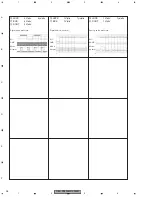
Page 36: ... F A B E LRCK BCK DOUT 2V div 2V div 2V div 5µs div Digtal audio waveform Ref GND Mode Normal LRCK DOUT 1V div 1V div 1µs div Ref AGND Mode Normal LRCK BCK 1V div 1V div 1µs div Digtal audio waveform Analog audio waveform Ref GND Mode Normal ...

Page 37: ...DEH P9600MP XN EW 37 5 6 7 8 5 6 7 8 C D F A B E ...

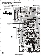
Page 38: ...TUNER AMP UNIT SIDE B SIDE A NOTE FOR PCB DIAGRAMS 1 The parts mounted on this PCB include all necessary parts for several destination For further information for respective destinations be sure to check with the schematic dia gram 2 Viewpoint of PCB diagrams FRONT IP BUS B CN1801 D CN902 CORD ASSY TEL WIRED REMOTE CONTROL ANTENNA CABLE ...

Page 39: ...DEH P9600MP XN EW 39 5 6 7 8 5 6 7 8 C D F A B E A SIDE A IC Q RCA FRONT IP BUS E M951 AUTOMATIC FLAP MOTOR DSP MODE F D CN901 FM AM TUNER UNIT NNA CABLE ...

Page 40: ...DEH P9600MP XN EW 40 1 2 3 4 1 2 3 4 C D F A B E A A TUNER AMP UNIT IC Q PCL ...

Page 41: ...DEH P9600MP XN EW 41 5 6 7 8 5 6 7 8 C D F A B E A SIDE B ...

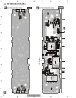
Page 42: ...DEH P9600MP XN EW 42 1 2 3 4 1 2 3 4 C D F A B E 4 2 KEYBOARD UNIT OEL B B KEYBOARD UNIT OEL B KEYBOARD UNIT OEL SIDE A SIDE B IC Q A CN871 AUDIO FUNC DISP ENT OEL MODULE ...

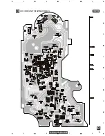
Page 43: ...DEH P9600MP XN EW 43 5 6 7 8 5 6 7 8 C D F A B E 4 3 KEYBOARD UNIT LCD C C KEYBOARD UNIT LCD C KEYBOARD UNIT LCD SIDE A SIDE B IC Q IC Q F EJECT EQ TA 1 2 3 4 5 6 RESET BAND TEXT OPEN SOURCE VOLUME ...

Page 44: ...DEH P9600MP XN EW 44 1 2 3 4 1 2 3 4 C D F A B E 4 4 CD MECHANISM MODULE D D CD CORE UNIT S10WMACODE2 SIDE A A CN701 A CN703 M1 SPINDLE MOTOR M2 LOADING CARRIAGE MOTOR PICKUP UNIT P10 SERVICE HOME ...

Page 45: ...DEH P9600MP XN EW 45 5 6 7 8 5 6 7 8 C D F A B E D D CD CORE UNIT S10WMACODE2 SIDE B CLAMP DSCSNS 8EJ 12EJ ...

Page 46: ...DEH P9600MP XN EW 46 1 2 3 4 1 2 3 4 C D F A B E 4 5 SWITCH PCB GREEN E SWITCH PCB SIDE A E E SWITCH PCB SIDE B A CN811 S951 S952 S953 OPEN CLOSE EJECT YELLOW BLACK BLUE ...

Page 47: ...DEH P9600MP XN EW 47 5 6 7 8 5 6 7 8 C D F A B E 4 6 CONNECTOR PCB 1 2 3 4 5 6 7 8 9 10 11 12 13 F F F CONNECTOR PCB F CONNECTOR PCB SIDE A SIDE B C CN1901 A CN872 1 5 10 13 ...

Page 48: ...nsistor 2SD1767 Q 692 Transistor IMD2A Q 741 Transistor IMD2A Q 742 Transistor 2SD2396 Q 743 Transistor 2SD1767 Q 744 Transistor IMD2A Q 751 Transistor 2SC3052 12 Q 752 Transistor IMD2A Q 811 Transistor 2SD1760F5 Q 812 Transistor IMD3A Q 833 Transistor DTC114EU Q 834 Transistor 2SC2412K Q 835 Transistor IMD2A Q 841 Transistor 2SD1760F5 Q 842 Transistor IMD2A Q 851 Transistor 2SB808 Q 852 Transisto...

Page 49: ...0kΩ B CCP1229 FU351 Fuse 3A CEK1286 MIC321 Microphone CPM1011 BZ381 Buzzer CPV1062 FM AM Tuner Unit CWE1645 RESISTORS R 101 RS1 16S562J R 102 RS1 16S332J R 103 RS1 16S181J R 104 RS1 16S181J R 105 RS1 16S223J R 106 RS1 16S223J R 107 RS1 16S102J Circuit Symbol and No Part No R 108 RS1 16S102J R 109 RS1 16S222J R 110 RS1 16S101J R 111 RS1 16S101J R 112 RS1 16S102J R 113 RS1 16S150J R 114 RS1 16S470J ...

Page 50: ...23J R 360 RS1 16S223J R 361 RS1 16S223J R 362 RS1 16S223J R 363 RS1 16S471J R 364 RS1 16S471J Circuit Symbol and No Part No R 365 RS1 16S471J R 366 RS1 16S471J R 367 RS1 16S471J R 368 RS1 16S471J R 369 RS1 16S103J R 370 RS1 16S103J R 371 RS1 16S103J R 372 RS1 16S103J R 373 RS1 16S103J R 374 RS1 16S103J R 381 RS1 16S102J R 389 RS1 16S102J R 391 RS1 16S102J R 392 RS1 16S104J R 401 RS1 16S681J R 402 ...

Page 51: ... R 882 RS1 16S473J R 883 RS1 16S104J R 884 RS1 16S473J R 901 RS1 16S223J R 902 RS1 16S272J R 922 RS1 16S821J Circuit Symbol and No Part No R 923 RD1 4PU182J R 924 RS1 16S223J R 925 RS1 16S223J R 931 RS1 16S104J R 932 RS1 16S473J R 933 RS1 16S103J R 934 RS1 16S473J R 935 RS1 16S472J R 943 RS1 16S103J R 951 RS1 16S102J R 952 RS1 16S472J R 953 RS1 16S472J R 954 RS1 16S153J R 961 RS1 16S151J R 962 RS1...

Page 52: ...YB104K25 C 312 CEHAR100M16 C 313 CKSQYB225K10 C 314 CKSQYB225K10 C 321 CKSRYB105K10 C 322 CKSRYB105K10 Circuit Symbol and No Part No C 325 CCSRCH101J50 C 326 CKSRYB105K10 C 327 CEALNP4R7M16 C 328 CKSRYB105K10 C 329 CEALNP4R7M16 C 330 CKSRYB474K10 C 331 CKSRYB104K25 C 332 CEAL100M16 C 333 CKSRYB105K10 C 334 CKSRYB105K10 C 351 CEJQ100M50 C 352 CEJQ100M50 C 353 CEJQ100M50 C 354 CEJQ100M50 C 355 CEJQ1...

Page 53: ... IC PD5917A IC 1806 IC PD8122A Circuit Symbol and No Part No IC 1807 IC PD6460A IC 1808 IC TC7WH32FK D 1803 Diode 1SS355 D 1808 LED SML310BA1T D 1809 LED SML310BA1T D 1810 LED SML310BA1T D 1811 LED SML310BA1T L 1801 Inductor CTF1530 L 1802 Inductor CTF1484 L 1803 Inductor CTF1530 L 1804 Chip Felight Beads CTF1399 X 1801 Radiator 10 0MHz CSS1577 S 1801 Push Switch CSG1111 S 1802 Push Switch CSG1111...

Page 54: ... 1904 Push Switch CSG1111 S 1905 Push Switch CSG1111 S 1906 Push Switch CSG1111 S 1907 Push Switch CSG1111 S 1908 Push Switch CSG1111 S 1909 Push Switch CSG1111 Circuit Symbol and No Part No S 1911 Push Switch CSG1111 S 1912 Push Switch CSG1111 S 1913 Push Switch CSG1111 S 1914 Push Switch CSG1111 S 1915 Push Switch CSG1111 S 1916 Push Switch CSG1111 S 1917 Push Switch CSG1111 S 1918 Push Switch C...

Page 55: ... 224 RS1 16SS0R0J R 225 RS1 16SS103J R 226 RS1 16SS393J R 227 RS1 16SS562J R 228 RS1 16SS122J R 229 RS1 16SS472J Circuit Symbol and No Part No R 231 RS1 16SS0R0J R 232 RS1 16SS122J R 233 RS1 16SS0R0J R 237 RS1 16SS221J R 238 RS1 16SS221J R 239 RS1 16SS221J R 240 RS1 16SS0R0J R 241 RS1 16SS333J R 243 RS1 16SS333J R 245 RS1 16SS333J R 250 RS1 16SS0R0J R 256 RS1 16SS0R0J R 261 RS1 16S0R0J R 262 RS1 1...

Page 56: ...SCH5R0C50 C 224 CKSSYB104K10 C 225 CKSSYB103K16 C 226 CCSSCH680J50 C 227 CCSSCH470J50 C 228 CKSSYB682K25 C 230 CKSSYB104K10 C 232 CKSSYB104K10 C 233 10µF 6 3V CCH1470 C 234 220µF 4V CCH1590 C 235 CKSRYB224K16 C 237 CKSSYB104K10 C 239 CCSSCH330J50 C 242 CKSSYB104K10 Circuit Symbol and No Part No C 246 CKSSYB104K10 C 249 CKSSYB221K50 C 250 CKSRYB102K50 C 251 CKSRYB102K50 C 260 CKSSYB104K10 C 301 CKS...

Page 57: ...DEH P9600MP XN EW 57 5 6 7 8 5 6 7 8 C D F A B E 6 ADJUSTMENT 6 1 JIG CONNECTION DIAGRAM Rubber Band Rubber Band GGD1292 To CD Mechanism Module CN703 CN872 CN1901 KEYBOARD UNIT LCD TUNER AMP UNIT ...

Page 58: ...ections will not work Avoid applying any mechanical or electrical shock to the mechanism during adjustment The RFI and RFO signals with a wide frequency range are easy to oscillate When observing the signals insert a resistor of 1k ohms in series The load and eject operation is not guarantied with the mechanism upside down If the mechanism is blocked due to mistaken eject operation reset the produ...

Page 59: ...N9xSEC9x Key BAND 6 1 2 3 Power On Off CRG TR Jump Direction of the external surface CRG TR Jump Direction of the internal surface T CLS and AGC and Applicable servomechanism AGC AGC display switching RF Gain switching Offset adjustment display T Balance adjustment T Open F Close S Curve Rough Servo and RF AGC F T RF AGC SPDL 1X 2X switching As for the double speed 2x audio output cannot be suppor...

Page 60: ...d switch the 3V regulator on 2 Using the and buttons move the PU unit to the innermost track 3 Press key 3 to close focus the display should read 91 Press key 2 to implement the tracking balance adjustment the display should now read 81 Press key 3 The display will change returning to 81 on the fourth press 4 As shown in the diagram above monitor the LPF outputs using the oscilloscope and check th...

Page 61: ...DEH P9600MP XN EW 61 5 6 7 8 5 6 7 8 C D F A B E Grating waveform 45 0 75 60 30 90 Ech Xch 20mV div AC Fch Ych 20mV div AC ...

Page 62: ...h or CRG move mechanism Communication error between microcomputer and SERVO LSI 11 Electricity Focus Servo NG Focusing not available Stains on rear side of disc or excessive vibrations on REWRITABLE 12 Electricity Spindle Lock NG Spindle not locked Sub code is strange not readable Subcode NG Failure on spindle stains or damages on disc or excessive vibrations A disc not containing CD R data is fou...

Page 63: ...19Hz If the clock signal is out of the range the X tal X601 should be replaced with new one OEL Screensaver Studio is an application to create OEL display image file The customer write the image file on a CD R disc and install it to car audio This function is similar to PC link kit CD PC1 OEL Screensaver Studio is available to the public on the PIONEER Home Page This software GGV1168 is added LKA ...

Page 64: ...rew and then remove the Case Unit Remove the four screws Removing the CD Mechanism Module Fig 2 1 1 Fig 1 Fig 2 Removing the Case Unit Fig 1 1 1 1 1 CD Mechanism Module Disconnect the connector and then remove the CD Mechanism Module 1 Case Unit Release the latches in order of the number indicated in Fig 1 1 2 3 4 5 ...

Page 65: ...nector and then remove the Grille Assy Panel Unit 1 1 Fig 5 Fig 4 the other side the other side OPEN POSITION EJECT POSITION CLOSE POSITION OPEN CLOSE Fig 3 Use the finger Rotate the gear in the direction indicated by arrow in Fig 3 until the Arm Unit moves to the 3 positions of a Fig 3 Moving the Arm Unit position Fig 3 Move the Arm Unit to the OPEN POSITION Fig 3 Move the Arm Unit to the EJECT P...

Page 66: ...emove or intall the Gear Unit do so with the Arm Unit in the CLOSE POSITION 1 When you disassemble or assemble the Gear Unit do so with the Arm Unit in the CLOSE POSITION Make sure that the Arm Unit is in the CLOSE POSITION by seeing the other side of the unit through the fully circular hole shown in the figure 2 When you install the motor fix the screws holding the motor in the direction of the a...

Page 67: ... remove the Gear Unit Fig 6 then Tuner Amp Unit and the other is to remove the Panel Unit Fig 5 then Tuner Amp Unit Remove the screw 2 Remove the two screws 3 Straighten the tabs at two locations indicated 4 Remove the two screws and then remove the Tuner Amp Unit 5 The Tuner Amp Unit may appear slightly different to the unit shown at right 1 1 2 3 3 4 4 5 5 Tuner Amp Unit 1 ...

Page 68: ...th Tooth CXB7959 CXB7960 CNC9679 CNC9678 1 Drive Unit Lubricants Points Both sides Both sides Grease GEM1013 Application to all points Slot Slot Shaft Field Slot Slot Slot Slot Slot Slot Slot Slot Slot Slot Shaft Shaft Shaft Field Field Field Boss Boss Tooth ...

Page 69: ...DEH P9600MP XN EW 69 5 6 7 8 5 6 7 8 C D F A B E 2 Case Unit CXC2406 Lubricants GEM1056 Application to all points Slot Slot Both sides Both sides ...

Page 70: ...he two springs C and the four screws 2 To remove the upper frame open it on the fulcrum A 3 While lifting the carriage mechanism remove the three dampers 4 With the frames removed insert the connectors coming from the main unit and eject the disc Caution Before installing the carriage mechanism in the frames be sure to apply some alcohol to the dampers and set the mechanism to the clamp mode Do no...

Page 71: ...ead wires from the inner holder 4 Remove the washer styling holder change arm and pickup lock arm 5 While releasing from the hook of the inner holder lift the end of the feed screw Caution In assembling move the planet gear to the load eject position before setting the feed screw in the inner holder Shorting Solder Planet Gear Change Arm Inner Holder Styling Holder Feed Screw Washer Pickup Lock Ar...

Page 72: ...8 10 12 14 16 1 3 5 7 9 11 13 15 1 B UP 2 GND 3 ILM 4 B REM 5 ACC 6 NC 7 NC 8 MUTE 9 RL 10 FL 11 RL 12 FL 13 RR 14 FR 15 RR 16 FR 1 2 11 12 1 FL 2 FLGND 3 FR 4 FRGND 5 RL 6 RLGND 7 RR 8 RRGND 9 SWL 10 SWLGND 11 SWR 12 SWRGND 1 BUS 2 GND 3 GND 4 NC 5 BUS 6 GND 7 BUS L INPUT 8 ASENB 9 BUS R INPUT 10 BUS R INPUT 11 BUS L INPUT 11 10 9 8 7 6 5 4 3 2 1 ...

Page 73: ...ut 24 PEE O PEE output 25 RDS57K 26 ROMCS O O ROM collection chip select output 27 ROMCK ROM collection clock output 28 ROMDATA I O ROM collection data input output 29 IPBUSIN I IP BUS input 30 IPBUSOUT O IP BUS output 31 DPDT1 O OEL display microcomputer communicator data output 32 KYDT1 I OEL display microcomputer communicator data input 33 34 NC Not used RDS clock input RDS PLL lock detection i...

Page 74: ...put 69 fclssw I Auto flap close sense input 70 FLPILM O Disc loading slot illumination output 71 pce PLL chip enable input 72 PCE I I O O O PLL chip enable input 73 bsens I Back up sense input 74 asens I ACC sense input 75 NC Not used DSP chip select intput EVOL chip select intput Not used Not used Not used 76 77 78 DSP_CS EVOL_CS NC 79 SWVDD2 O LCD S MODE output display microcomputer power supply...

Page 75: ...tilevel Modulator DAC Serial Input I F Function Control I F System Clock BCK LRCK DATA1 1 2 Zero Detect Power Supply DATA2 3 4 DATA3 5 6 DEMP1 DEMP0 FMT1 SCKI FMT0 DAC Output Amp and DAC DAC Output Amp and DAC Output Amp and DAC Output Amp and VOUT1 ZEROA V CC AGND VOUT2 VOUT3 VCOM VOUT4 VOUT5 VOUT6 Low Pass Filter Low Pass Filter Low Pass Filter Low Pass Filter Low Pass Filter Output Amp and BD48...

Page 76: ... pin for digital section 3 3V typ 22 DVSS Ground pin for digital section 0V 23 24 CLKO1 2 O Clock output pin 25 XTO O Crystal oscillator output pin 26 XTI I Master clock input pin 27 DVSS Ground pin for digital section 0V 28 DVDD Power supply pin for digital section 3 3V typ 29 SMODE I Slave Master mode selector pin 30 SO O Serial data output pin for Microcomputer interfaces 31 SI I Microcomputer ...

Page 77: ...DEH P9600MP XN EW 77 5 6 7 8 5 6 7 8 C D F A B E 1 3 2 S1 R S2 GND BUS BUS VCC STB 4 5 6 7 8 BIAS DRIVER OUTPUT COM RECEIVER OUTPUT 1 2 3 4 1A 1B 2Y GND VCC 1Y 2B 2A 8 7 6 5 HA12240FP TC7WH32FK ...

Page 78: ...ed Not used Not used Not used Not used Not used Not used Not used Not used Not used 31 CLK1 I Clock input 32 RS2 O Read signal output 33 D0_L O 34 NC 35 CLK0 I Clock input 36 RS1 Read signal 37 38 NC 40 NC 39 hold Pull up Pull up 41 BCLK 42 rd O O Read strobe output 43 NC 44 wr Write output 45 48 cs O ROM chip select output 49 A19 O Address bus output Address bus output Address bus output Address ...

Page 79: ...t 15 16 KDT0 1 Key data intput Analog 17 REM I Remote control data input 18 DPDT I I I Display data input 19 NC Not used 20 KYDT O Key data output 21 MODA GND 22 X0 Crystal oscillating element connection pin Crystal oscillating element connection pin 23 X1 24 VSS GND 25 26 KDT2 3 Key data input 27 NC Not used 28 KST4 O Key strobe output 29 33 NC Not used 34 55 SEG31 10 O LCD segment signal output ...

Page 80: ...7 3 1 Address input Data output Chip enable input Output enable Power supply GND PD8122A PD6460A A12 A11 A10 A9 A8 NC NC we reset NC NC RY by NC A17 A7 A6 A5 A4 A3 A2 A1 VSS DQ15 A1 DQ7 DQ14 DQ6 DQ13 DQ5 DQ12 DQ4 VCC DQ11 DQ3 DQ10 DQ2 DQ9 DQ1 DQ8 DQ0 oe VSS ce A0 A0 A17 DQ0 DQ15 ce oe we RY by Address input Data output Chip enable input Output enable input Write enable input Ready Busy output A15 ...

Page 81: ...41 TEST3 1 I Connected to GND 42 PWMSW1 I Setup 1 for PWM output FD TD 43 TESTEN I Connected to GND 44 D1 GND GND for 1 6V digital circuits 45 DIN I Input of audio data 46 DOUT O Output of audio data 47 SCKIN I Clock input for audio data 48 SCKO O Clock output for audio data 49 LRCKIN I Input of LRCK for audio data 50 LRCK O Output LRCK for audio data 51 xtalen I Permission to oscillate 16 9344MHz...

Page 82: ...GCO O Output of RF 117 C3T O Connection to the capacitor for detecting 3T 118 AGCI I Input of AGC 119 RFO O Output of RF AGC 120 121 EQ2 1 I Equalizer 2 1 122 RF2 I Reversal input of RF2 123 RF I Reversal input of RF 124 A GND Ground for the analog system 125 A I Input of A 126 C I Input of C 127 B I Input of B 128 D I Input of D 129 F I Input of F 130 E I Input of E 131 VREFIN I Input of referenc...

Page 83: ... O C It is possible to receive P Bus 28 bsrq I O C P Bus service request demand 29 dspok I DSP microcomputer initialization OK input 30 DSCSNS S903 I Disc state sense input 31 8EJ S905 I Input of detection of 8 cm disc ejection 32 12EJ S904 I Input of detection of 12 cm disc ejection 33 EVSS E power supply GND 34 EVDD E power supply Positive power supply 35 36 SRAMLEVEL0 1 O C SRAM level meter out...

Page 84: ...5 87 90 NC Not used 91 93 A D For changer A D 94 csens I Flap closing sense input 95 TYPE_A D I CD DA analog digital output change setup 96 testin I Chip check test program starting input 97 HOME I Home SW sense input 98 TEMP Temperature information sense input 99 VDSENS VD power supply short sense input 100 NC Not used PE5423A 25 26 50 51 75 76 100 1 Format Meaning C CMOS 1 2 3 VIN VOUT VSS Refer...

Page 85: ...ower supply pin for CH1 CH2 and CH3 at Power stage 11 VO1 Driver CH1 Negative output 12 VO1 Driver CH2 Positive output 13 VO2 Driver CH2 Negative output 14 VO2 Driver CH2 Positive output 15 VO3 Driver CH2 Positive output 16 VO3 Driver CH2 Negative output 17 VO4 Driver CH4 Positive output 18 VO4 Driver CH4 Negative output 19 POWVCC2 Power supply pin for CH4 at Power stage 20 GND Ground pin 21 CNT C...

Page 86: ...supply Power supply for EEPROM pin 13 is connected with a power supply of micro computer 14 DO O data out Data output 15 DGND digital ground Ground of digital block 16 NC non connection Not used 17 VDD_3 3 power supply The power supply for digital block 3 3V 0 2V 18 RDS_CK O RDS clock Output of RDS clock 2 5V 19 RDS_DATA O RDS data Output of RDS data 2 5V 20 RDS_LOCK O RDS lock Output unit High ac...

Page 87: ...EW 87 5 6 7 8 5 6 7 8 C D F A B E 7 2 2 DISPLAY 36 35 34 33 32 31 30 29 28 27 26 25 24 23 22 21 20 19 18 17 16 15 14 13 12 11 10 9 8 7 6 5 4 COM0 3 COM1 2 COM2 1 COM3 4 COM0 3 COM1 2 COM2 1 COM3 CAW1704 SEGMENT COMMON ...

Page 88: ... LCD ASENBO H Pin 82 Source keys operative Completes power on operation After that proceed to each source operation SYSPW H Pin 23 Starts communication with Grille microcomputer Source ON 300ms 300ms In case of the above signal the communication with Grille microcomputer may fail If the time interval is not 300msec the oscillator may be defective asens Pin 74 ...

Page 89: ... C D F A B E 7 4 CLEANING Before shipping out the product be sure to clean the following portions by using the prescribed cleaning tools Portions to be cleaned Cleaning tools CD pickup lenses Cleaning liquid GEM1004 Cleaning paper GED 008 ...

Page 90: ...DEH P9600MP XN EW 90 1 2 3 4 1 2 3 4 C D F A B E 8 OPERATIONS ...

Page 91: ...DEH P9600MP XN EW 91 5 6 7 8 5 6 7 8 C D F A B E ...

Page 92: ...DEH P9600MP XN EW 92 1 2 3 4 1 2 3 4 C D F A B E ...

Page 93: ...DEH P9600MP XN EW 93 5 6 7 8 5 6 7 8 C D F A B E ...

Page 94: ...4 1 2 3 4 1 2 3 4 C D F A B E Fixing the front panel If you do not operate the removing and attaching the front panel function use the supplied fixing screws to fix the front panel to this unit F BPZ20P060FZK ixing screw ...

Page 95: ...ignition switch position 18 Red 5 Accessory or back up 15 Yellow 3 Back up or accessory 14 Cap 1 When not using this terminal do not remove the cap Note Depending on the kind of vehicle the function of 3 and 5 may be different In this case be sure to connect 2 to 5 and 4 to 3 13 Connect leads of the same color to each other 37 Subwoofer 35 Front speaker 36 Rear speaker 37 Subwoofer 35 Front speake...

Page 96: ...DEH P9600MP XN EW 96 1 2 3 4 1 2 3 4 C D F A B E Jigs list Disc ABEX TCD 782 Cleaning liquid GEM1004 Cleaning paper GED 008 Cord GGD1292 ...

Reviews: