


68
DEH-P640,P6400,P6450
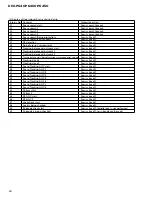
Pin No.
Pin Name
I/O
Function and Operation
72
TUNPCE
O
TUNER:Chip enable output(PLL)
73
BSENS
I
Backup sense
74
ASENS
I
ACC sense
75
NC
Not used
76
LOCH
O
TUNER:Local H output
77
LOCL
O
TUNER:Local L output
78
XPCK
O
CD:LSI clock output
79
XCE
O
CD:LSI chip enable output
80
XRST
O
CD:LSI reset output
81
IPPW
O
IPBUS:Driver power supply control output
82
ASENBO
O
IPBUS:Slave ACC sense output
83
ISENS
I
Illumination sense input
84, 85
MODEL1, 0
I
Model input 1, 0
86
NC
Not used
87
MUTE
O
Mute output
88
TESTIN
I
Test program input
89
DSCSNS
I
CD:Disc position detection input
90
VDSENS
I
CD:VD power supply sense input
91
TEMP
I
CD:Temperature sense input
92
LVLINR
I
Level indicator R ch input
93
CSENS
I
Flap open/close sense input
94
LVLINL
I
Level indicator L ch input
95
NC
Not used
96
AVSS
AD converter power supply input(Vss)
97
SL
I
TUNER:Signal level input
98
VREF
AD converter reference voltage(Vref)
99
AVCC
AD converter power supply input(Vcc)
100
TUNPDI
I
TUNER:Data input
*PD5699A
30
31
50
51
80
81
100
1
IC's marked by * are MOS type.
Be careful in handling them because they are very
liable to be damaged by electrostatic induction.
Summary of Contents for DEH-P6400
Page 6: ...6 DEH P640 P6400 P6450 2 2 PACKING DEH P6450 13 18 16 1 11 15 17 10 9 8 14 4 6 7 5 2 3 12 ...
Page 8: ...8 DEH P640 P6400 P6450 2 3 EXTERIOR ...
Page 11: ...11 DEH P640 P6400 P6450 ...
Page 12: ...12 DEH P640 P6400 P6450 2 4 CD MECHANISM MODULE D GEM1035 GEM1035 GEM1040 ...
Page 36: ...36 DEH P640 P6400 P6450 A 1 2 3 4 B C D 1 2 3 4 A IC Q A TUNER AMP UNIT ...
Page 37: ...DEH P640 P6400 P6450 5 6 7 8 A B C D 5 6 7 8 37 2 3 4 1 7 6 5 8 SIDE B A ...
Page 41: ...41 DEH P640 P6400 P6450 1 2 3 4 A B C D 1 2 3 4 CLAMP 8EJ SIDE B CONTROL UNIT D D ...


