

DEH-P7200HD/XNUC
12
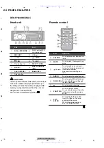
1
2
3
4
1
2
3
4
C
D
F
A
B
E
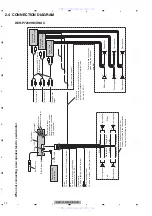
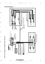
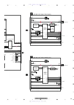
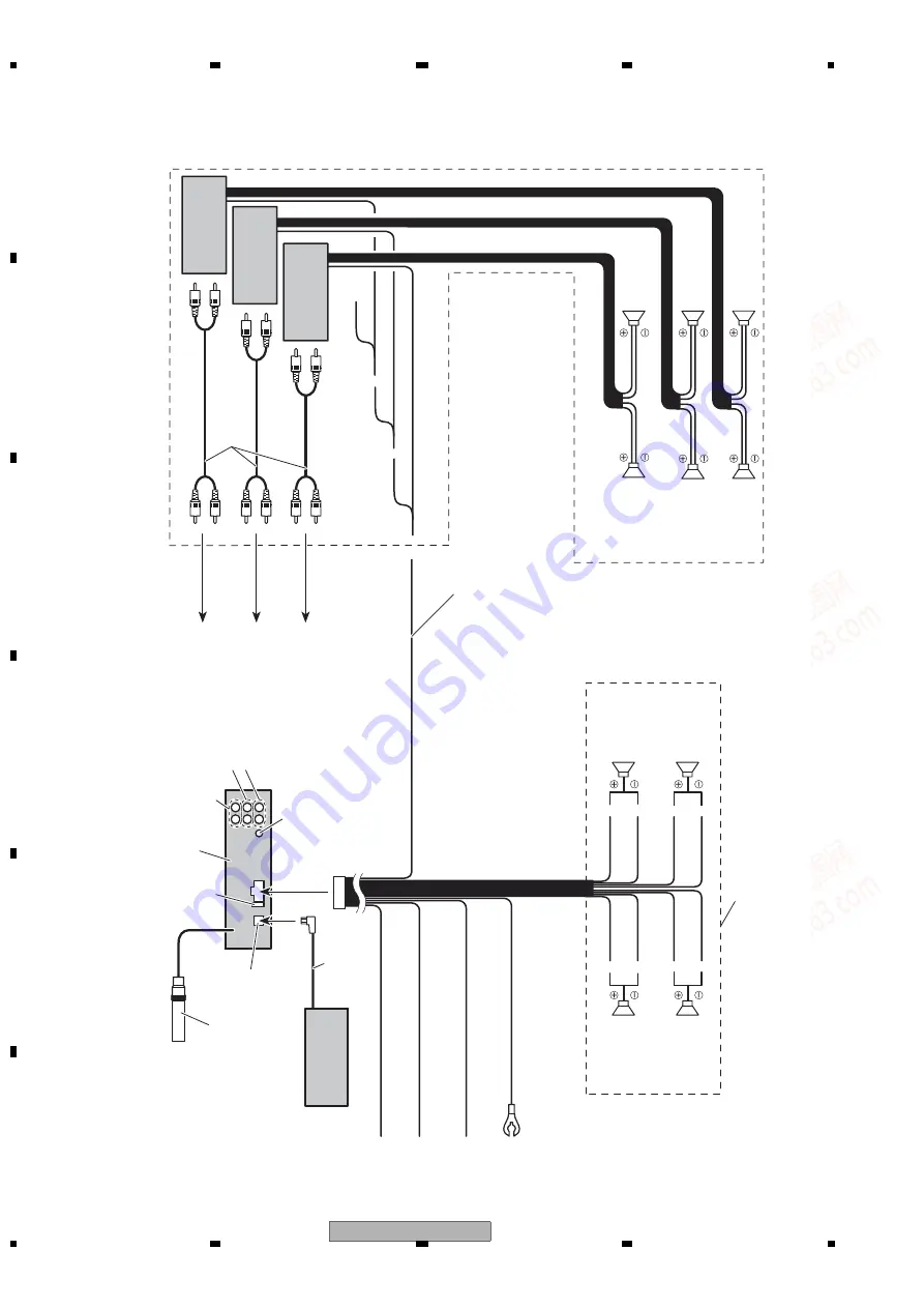
2.4 CONNECTION DIAGRAM
When not connecting a r
Y
ellow
Connect to the constant 12 V supply terminal.
Red
Connect to terminal contr
olled by
ignition switch (12 V DC).
Orange/white
Connect to lighting switch terminal.
Black (chassis gr
ound)
Connect to a clean, paint-fr
ee metal location.
Fr
ont output
Subwoofer output
Right
Left
W
ith a 2 speaker system, do not
connect anything to the speaker leads
that ar
e not connected to speakers.
Front speaker
Front speaker
Rear speaker
Rear speaker
White
Gray
Gray/black
White/black
Gr
een
Violet
Gr
een/black
Violet/black
Rear output
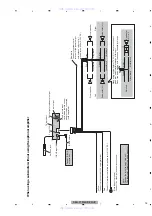
IP-BUS input (Blue)
IP-BUS cable
Pioneer IP-BUS
accessories
W
ir
ed
remote input
H
ar
d-wir
ed
remote contr
ol
adaptor can be connected
(sold separately).
Antenna jack
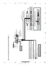
Power amp
(sold separately)
Connect with RCA cables
(sold separately)
Perform these connections
when using the optional
amplifier
.
System
remote contr
ol
Blue/white
Connect to system contr
ol terminal of the power
amp or auto-antenna r
elay contr
ol terminal (max.
300 mA 12 V DC).
Power amp
(sold separately)
Fr
ont speaker
Power amp
(sold separately)
T
o subwoofer
output
T
o fr
ont output
T
o
rear output
Fr
ont speaker
Rear speaker
Rear speaker
Subwoofer
Subwoofer
DEH-P7200HD/XNUC
www. xiaoyu163. com
QQ 376315150
9
9
2
8
9
4
2
9
8
TEL 13942296513
9
9
2
8
9
4
2
9
8
0
5
1
5
1
3
6
7
3
Q
Q
TEL 13942296513 QQ 376315150 892498299
TEL 13942296513 QQ 376315150 892498299


