64
DEH-P300,P3000,P200
7.2 DIAGNOSIS
7.2.1 DISASSEMBLY
-
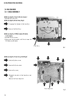
Removing the Tuner Amp Unit(Fig.2)
Remove the two screws.
Remove the three screws.
Remove the screw.
Straighten the tabs at four locations indi-
cated.
Remove the Tuner Amp Unit.
-
Removing the Case Unit(not shown)
1. Remove the Case Unit.
-
Removing the Panel Assy(Fig.1)
Disengage the stoppers at two locations.
Remove the Panel Assy.
-
Removing the CD Mechanism Module
(not shown)
1. Remove the four screws.
2.Disconnect the connector, and then remove the
CD Mechanism Module.
Fig.1
Fig.2
Panel Assy
Tuner Amp Unit
Summary of Contents for DEH-P200
Page 4: ...4 DEH P300 P3000 P200 2 2 EXTERIOR DEH P300 X1N UC ...
Page 6: ...6 DEH P300 P3000 P200 DEH P3000 X1N UC ...
Page 8: ...8 DEH P300 P3000 P200 DEH P200 X1N UC ...
Page 10: ...10 DEH P300 P3000 P200 2 3 CD MECHANISM MODULE ...
Page 15: ...15 DEH P300 P3000 P200 5 6 7 8 5 6 7 8 D C B A ANTENNA CABLE VD REGULATOR A a A a A b E D C ...
Page 17: ...17 DEH P300 P3000 P200 5 6 7 8 5 6 7 8 D C B A CEK1014 CEK1136 A b A a A b ...
Page 21: ...21 DEH P300 P3000 P200 5 6 7 8 5 6 7 8 D C B A ANTENNA CABLE VD REGULATOR A a A a A b E D C ...
Page 22: ...22 DEH P300 P3000 P200 1 2 3 4 1 2 3 4 D C B A RESET 3V 3V 4 3V 4 3V A a A b A b ...
Page 23: ...23 DEH P300 P3000 P200 5 6 7 8 5 6 7 8 D C B A CEK1014 CEK1136 100K 33K A b A a A b ...
Page 25: ...25 DEH P300 P3000 P200 5 6 7 8 5 6 7 8 D C B A KV1410 23 B ...
Page 33: ...33 DEH P300 P3000 P200 ...
Page 36: ...36 DEH P300 P3000 P200 1 2 3 4 1 2 3 4 D C B A A A TUNER AMP UNIT ...
Page 37: ...37 DEH P300 P3000 P200 5 6 7 8 5 6 7 8 D C B A A SIDE B ...
Page 39: ...39 DEH P300 P3000 P200 1 2 3 4 1 2 3 4 D C B A B B SIDE B FM AM TUNER UNIT ...
Page 41: ...41 DEH P300 P3000 P200 1 2 3 4 1 2 3 4 D C B A C C SIDE B KEYBOARD UNIT A CN651 ...
Page 43: ...43 DEH P300 P3000 P200 D C B A 1 2 3 4 1 2 3 4 CONTROL UNIT SIDE B D D ...
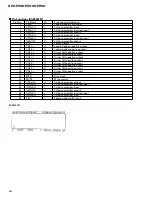
Page 63: ...63 DEH P300 P3000 P200 COMMON SEGMENT 7 1 2 DISPLAY CAW1497 CAW1500 ...


