41
DEH-M6156ZH,M6356ZH
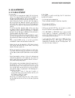
7.1.2 DISASSEMBLY
-
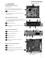
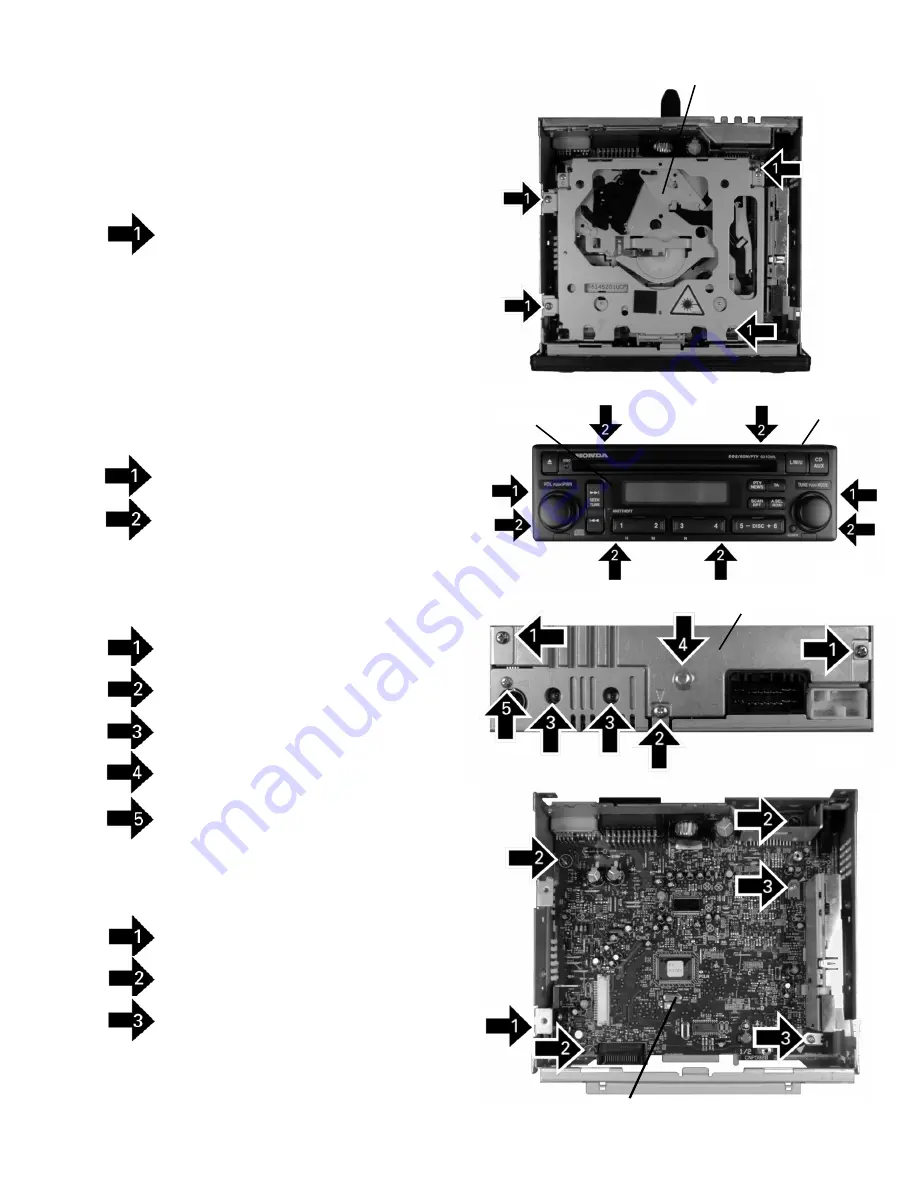
Removing the Heat Sink (Fig.3)
Remove the two screws(M3 x 12).
Remove the screw(M3 x 6).
Remove the two screws.
Remove the screw.
Remove the screw and then remove the
Heat Sink.
-
Removing the Case (not shown)
1. Remove the Case.
-
Removing the CD Mechanism Module (Fig.1)
Remove the four screws.
Disconnect the connector and then remove the CD
Mechanism Module.
-
Removing the Grille Assy (Fig.2)
The cushion has been stuck onto the frame of the Grille
Assy with double-faced adhesive tape. Remove the
cushion from the frame.
Remove the two screws.
Disconnect the six claws and then remove the
Grille Assy.
Fig.1
Fig.3
Fig.4
Tuner Amp Unit
Heat Sink
CD Mechanism Module
-
Removing the Tuner Amp Unit (Fig.4)
Remove the screw.
Straight the tabs at three locations indicated.
Remove the two screws and then remove the
Tuner Amp Unit.
Fig.2
Grille Assy
Cushion
Summary of Contents for DEH-M6156EW
Page 4: ...4 DEH M6156ZH M6356ZH 2 2 EXTERIOR A B ...
Page 6: ...6 DEH M6156ZH M6356ZH C D 2 3 CD MECHANISM MODULE ...
Page 21: ...21 DEH M6156ZH M6356ZH ...
Page 24: ...24 DEH M6156ZH M6356ZH 1 2 3 4 1 2 3 4 D C B A FRONT A A TUNER AMP UNIT ...
Page 25: ...25 DEH M6156ZH M6356ZH 5 6 7 8 5 6 7 8 D C B A A SIDE B ...
Page 27: ...27 DEH M6156ZH M6356ZH 1 2 3 4 1 2 3 4 D C B A B B KEYBOARD UNIT SIDE B A CN602 ...
Page 29: ...29 DEH M6156ZH M6356ZH D C B A 1 2 3 4 1 2 3 4 SIDE B C CLAMP CONTROL UNIT C ...
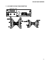
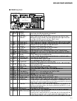
Page 45: ...45 DEH M6156ZH M6356ZH 7 1 3 CONNECTOR FUNCTION DESCRIPTION ANTENNA JACK ...


