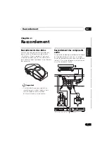
Connecting up
02
8
En
• Connect any other components (such as
an iPod
1
dock or a portable audio player) to
the
AUX
and
TUNER
inputs in the same
way.
2
Connect the analog outputs of your tape
deck (or other recorder) to the TAPE inputs
(IN) on this amplifier. Then connect the audio
inputs on the tape deck to the TAPE outputs
(OUT) on this amplifier.
This will allow you to make recordings from the
components connected to this amplifier. Use
stereo RCA phono cables as shown.
3
Turntables only:
Connect the audio
outputs of your turntable to the PHONO
inputs on this amplifier.
• If your turntable has a grounding wire,
secure it to the ground terminal on this
amplifier.
• If your turntable has line-level outputs (i.e.,
it has a built-in phono pre-amp), connect it
to the
AUX
inputs instead.
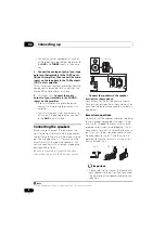
Connecting the speakers
Make sure you connect the speaker on the
right to the right terminal and the speaker on
the left to the left terminal. Also make sure the
positive and negative (+/–) terminals on the
amplifier match those on the speakers. You
can use speakers with a nominal impedance
between 4
Ω
to 16
Ω
.
Be sure to complete all connections before
connecting this unit to the AC power source.
•
Connect the speakers to the speaker
terminals as shown above.
Connections for the left speaker are shown.
Connect the right speaker in the same way. You
can use either bare wire connections to do this
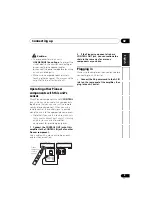
Bare wire connections
Make sure that the speaker cable you’re going
to use is properly prepared with about 10 mm
of insulator stripped from each wire, and the
exposed wire strands twisted together (
fig. A
).
To connect a terminal, unscrew the terminal a
few turns until there is enough space to insert
the exposed wire (
fig. B
). Once the wire is in
position, tighten the terminal until the wire is
firmly clamped (
fig. C
).
Important
• Please refer to the manual that came with
your speakers for details on how to connect
the other end of the speaker cables to your
speakers.
Note
1
iPod is a trademark of Apple Inc., registered in the U.S. and other countries.
PHONO
L
R
GND
AC IN
SPEAKER
L
SIGNAL
CONTROL
OUT
Left speaker
10 mm
fig. A
fig. B
fig. C
A6MK2_SYXCN5.book 8 ページ
009年4月7日 火曜日 午前
時
分
Summary of Contents for A-A6MK2-K
Page 43: ...Zusätzliche Informationen 05 15 De A6MK2_SYXCN5 De book Page 15 Monday April 13 2009 9 26 AM ...
Page 57: ...Bijkomende informatie 05 15 Nl A6MK2_SYXCN5 Nl book Page 15 Monday April 13 2009 10 39 AM ...
Page 85: ...Información adicional 05 15 Es A6MK2_SYXCN5 Es book Page 15 Monday April 13 2009 9 47 AM ...
Page 90: ...01 6 Ru Э К Э A6MK2_SYXCN5 Ru book Page 6 Monday April 13 2009 11 22 AM ...


