


PIN-M-02 DPMRA01.A Service Manual
Copyright © Pinssar (Aust) Pty Ltd 2019. The PINSSAR logo is a registered trademark of Pinssar Pty Ltd
Page 83 of
96
F
IGURE
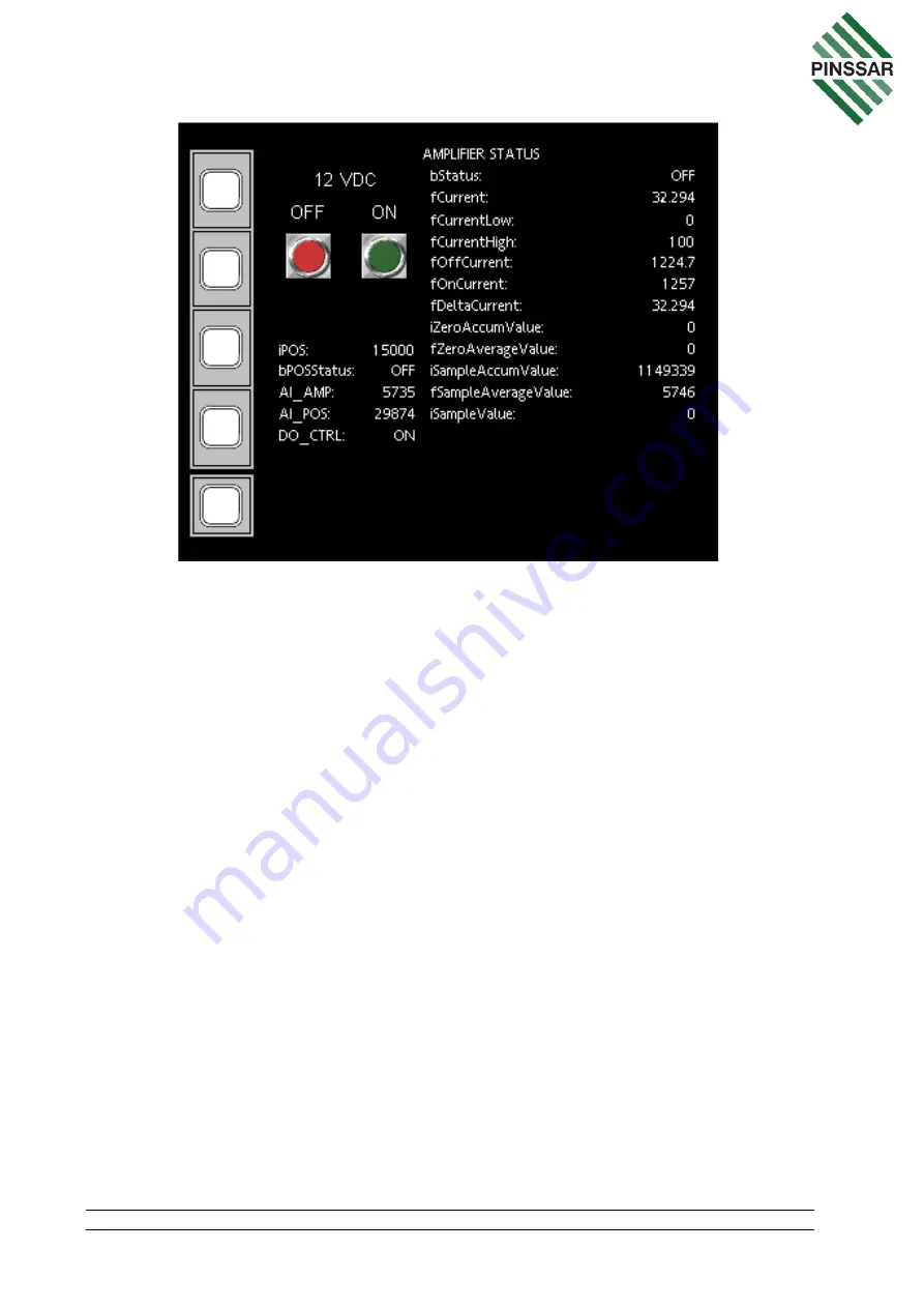
57
-
AMPLIFIER
STATUS
P
AGE
fCurrent on the AMPLIFIER STATUS page indicates the current consumption of the
amplifier during the last cycle. This value should be in the range of fCurrentLow (0mA)
and fCurrentHigh (100mA). Check if fCurrent is outside of this setpoint range and if so,
wait for two cycles to complete to see if the error is persistent.
If the error has not resolved, the Amplifier can be manually turned on. First put the DPM
Reader in standby mode as per Section 11.3 Then manually turn on the Amplifier with
the green ON button on the AMPLIFIER STATUS page. Check the status of the
Amplifier reading in HMI window on SYSTEM OVERVIEW page one level up by clicking
the button on the bottom left corner. Also check the voltage on the digital outputs out of
Relay No 8 on Phoenix Contact Relays using multimeter is 5VDC. Check the amplifier
connection on DPM carrier board.
After a cycle has run, check the fZeroAverageValue is between 5000 to 7500. If
outside of these limits, the value indicates a problem in DPM Amplifier board. The
DPM Amplifier board will need to be replaced, which will mean the 05-0773 Laser
Chamber Sub-assembly will need to be replaced as the laser chamber is calibrated to
the amplifier board. When the chamber is replaced the new calibration coefficient
etched on the laser chamber plate will need to be entered into the HMI software to
maintain the overall calibration of the DPM Reader as detailed in Section 6.8.
12.4 Sensor
From the SYSTEM OVERVIEW page, clicking on the SENSOR box will take the user
to the SENSOR STATUS page (Figure 58). This will allow operators to monitor and