


PIN-M-02 DPMRA01.A Service Manual
Copyright © Pinssar (Aust) Pty Ltd 2019. The PINSSAR logo is a registered trademark of Pinssar Pty Ltd
Page 77 of
96
Where the (IP Address of DPM Reader) will be specific to the DPM Reader
your network. Make sure you have http not https at the start of the address.
For Example:
for the default IP Address of a DPM
Reader.
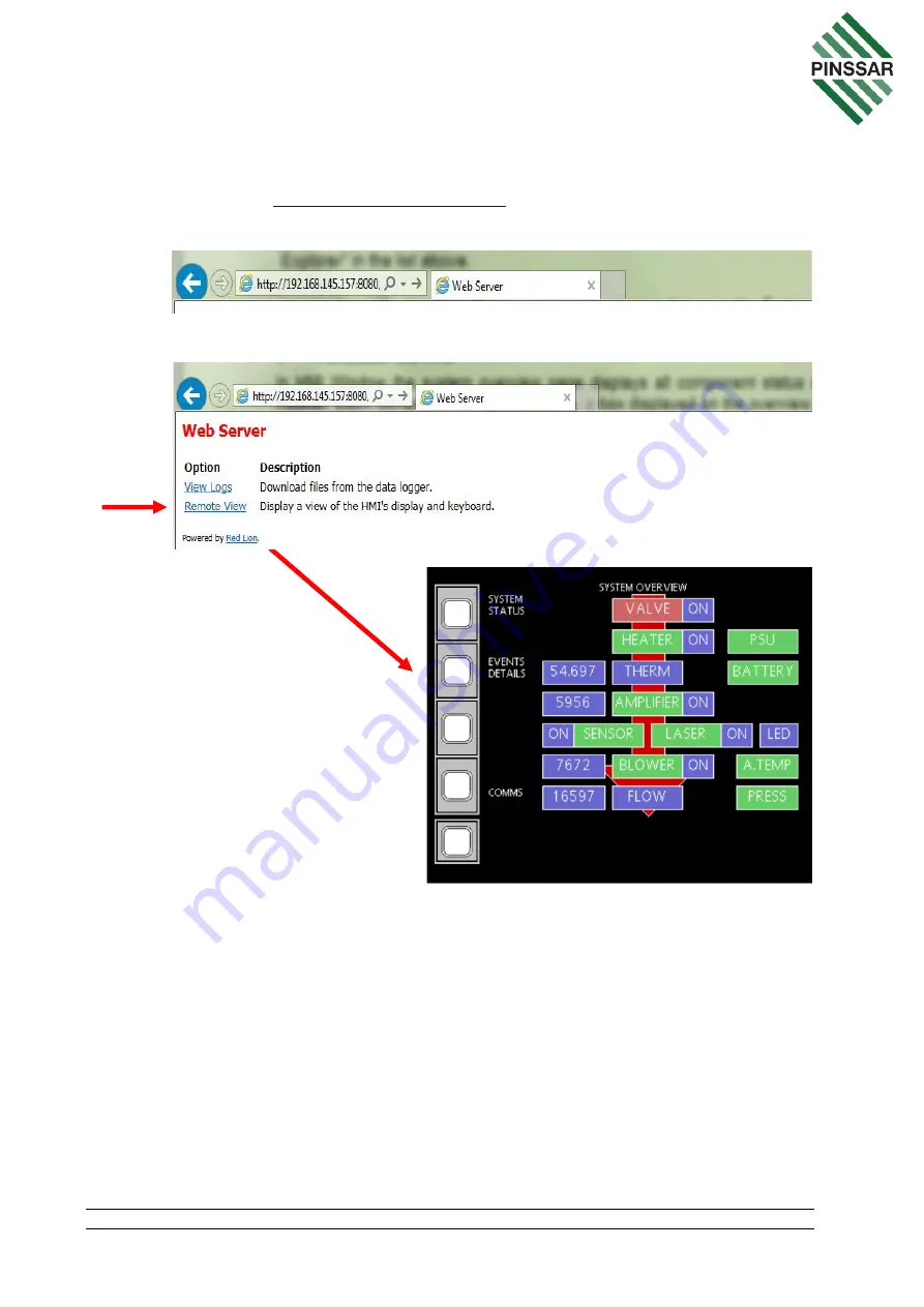
3. C
lick on “Remote View”.
11.2 HMI Navigation
The SYSTEM OVERVIEW page (Figure 51) will allow navigation to many different
screens to allow monitoring of the various components of the DPM Reader. The
following diagram (Figure 52) shows the various screens that can be accessed from the
buttons on the left-hand side of the SYSTEM OVERVIEW screen.
Clicking on the various component boxes on the other parts of the SYSTEM Overview
page will take users to screens that will enable further monitoring or user actions for the
various components. These will be described in further detail in Section 12.