background image

6.3

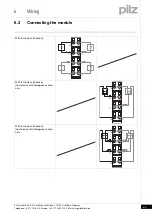
Connecting the module

6

Wiring

Pilz GmbH & Co. KG, Felix-Wankel-Straße 2, 73760 Ostfildern, Germany
Telephone: +49 711 3409-0, Telefax: +49 711 3409-133, E-Mail: [email protected]

6-6

With test pulses (checked)
Input device with diverse channels

I0

I2

I1

I3

21

11

22

12

23

13

24

14

T0

T0

T1

T1

Summary of Contents for PSSu E F 4DI

Page 1: ...Operating Manual No 21310 EN 04 Decentralised system PSSuniversal I O Operating Manual PSSu E F 4DI T R Operating Manual PSSu E F 4DI T R PSSu E F 4DI T R...

Page 2: ...es may be made for internal purposes Suggestions and comments for improving this documentation will be gratefully received Pilz PIT PMI PNOZ Primo PSEN PSS PVIS SafetyBUS p SafetyEYE SafetyNET p the s...

Page 3: ...ulations 3 3 3 2 1 Use of qualified personnel 3 3 3 2 2 Warranty and liability 3 3 3 2 3 Disposal 3 3 Chapter 4 Function description 4 1 Module features 4 1 4 1 1 Functions 4 1 4 1 2 Integrated protec...

Page 4: ...ral wiring guidelines 6 1 6 1 1 Mechanical connection of the base modules 6 1 6 2 Terminal configuration 6 3 6 3 Connecting the module 6 4 Chapter 7 Operation 7 1 Messages 7 1 7 2 Display elements 7 2...

Page 5: ...entation is intended for instruction and should be retained for future reference 1 1 2 Terminology System environment A and B Terminology System environment A and B 1 BA Einf Begriffsdefinition Sys A...

Page 6: ...is manual 2 Overview This chapter provides information on the product s most important fea tures 3 Safety This chapter must be read as it contains important information on safety and intended use 4 Fu...

Page 7: ...measures that can be taken WARNING This warning must be heeded It warns of a hazardous situation that could lead to serious injury and death and indicates preven tive measures that can be taken CAUTIO...

Page 8: ...1 Introduction Pilz GmbH Co KG Felix Wankel Stra e 2 73760 Ostfildern Germany Telephone 49 711 3409 0 Telefax 49 711 3409 133 E Mail pilz gmbh pilz de 1 4...

Page 9: ...function Details of the base modules that can be used are available in the chapter entitled Intended Use 2 1 1 Module features Module features 2 Geraetemerkmale_Zusatz BA Einleitung The product has th...

Page 10: ...1 LED for module diagnostics 2 Labelling strip with Name of electronic module Order Number Serial number Hardware version number 2D code 3 Labelling strip for the terminal configuration on the base m...

Page 11: ...les connection levels 1 2 3 and 4 With screw to loosen tighten the screw terminal on base modules with screw terminals With mechanism to operate the cage clamp on base modules with cage clamp terminal...

Page 12: ...2 Overview Pilz GmbH Co KG Felix Wankel Stra e 2 73760 Ostfildern Germany Telephone 49 711 3409 0 Telefax 49 711 3409 133 E Mail pilz gmbh pilz de 2 4...

Page 13: ...ased environmental requirements demanded by railway applications see Technical Details Bestimmung Gertebeschreibung_Ausschluss Intended use includes making the electrical installation EMC compliant Pl...

Page 14: ...he following base modules Bestimm_Basismodule Digital ohne C PSSu BP 1 8S PSSu BP 1 8C PSSu BP 1 12S PSSu BP 1 12C PSSu BP C1 1 12S PSSu BP C1 1 12C Bestimm_Verwend_Basismodule T R The PSSu E F 4DI T...

Page 15: ...Are familiar with the basic regulations concerning health and safety accident prevention Have read and understood the safety guidelines given in this descrip tion Have a good knowledge of the generic...

Page 16: ...3 Safety Pilz GmbH Co KG Felix Wankel Stra e 2 73760 Ostfildern Germany Telephone 49 711 3409 0 Telefax 49 711 3409 133 E Mail pilz gmbh pilz de 3 4...

Page 17: ...pulse outputs 2 test pulse outputs that use different test pulses test pulse 0 test pulse 1 Short circuit proof Current limitation Test pulses can be switched on or off Test pulses are switched off in...

Page 18: ...s Integrated protection mechanisms 4 Schutzmechanismen E A Module When the PSSu E F PS1 T is used to supply the system the module supply is buffered for 20 ms if the supply voltage is interrupted Schu...

Page 19: ...djacent bits of the same type configuration Further information on configuration is available in the PSSuniversal Configurator s online help 4 2 1 1 Addresses in the process image Addresses in the pro...

Page 20: ...ail pilz gmbh pilz de 4 4 4 2 2 PSSu assignment in system environment B PSSu assignment in system environment B 4 Funktionsbeschreibung_Zusatz I O Daten Sys B Data access is via pre defined I O data t...

Page 21: ...e also refer to the PSSuniversal Installation Manual Montage_EMV ESD 5 1 1 Dimensions Dimensions 5 Abmessungen 1xR 1xRL Base modules with four connection levels CAUTION Damage due to electrostatic dis...

Page 22: ...3760 Ostfildern Germany Telephone 49 711 3409 0 Telefax 49 711 3409 133 E Mail pilz gmbh pilz de 5 2 Base modules with six connection levels 12 6 mm 76 mm 52 1 mm 8 1 mm 67 7 mm 82 0 mm 71 8 mm 0 8 mm...

Page 23: ...For mechanical reasons it is not possible to mix base modules with screw terminals and base modules with cage clamp terminals All contacts should be protected from contamination The mechanics of the...

Page 24: ...inserted and removed when the load is switched off Unforeseeable error reactions may be triggered if modules are inserted and removed under load When an electronic module is plugged into a base modul...

Page 25: ...E Mail pilz gmbh pilz de 5 5 5 3 Inserting and removing an electronic module 5 Installation 5 3 2 Removing an electronic module Removing an electronic module 5 Elektronikmodul ziehen Procedure Press t...

Page 26: ...age BA Hot Swapping FS E Modul The electronic module can be hot swapped The configuration data is re tained when a module is swapped Effects System environment A In the event of a potential FS communi...

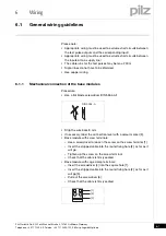
Page 27: ...s do not have to be shielded Use copper wiring 6 1 1 Mechanical connection of the base modules Mechanical connection of the base modules 6 Modulverdrahtung mech Procedure Use a flat blade screwdriver...

Page 28: ...Inputs outputs on the counter modules 1 5 mm2 AWG16 Analogue inputs outputs 1 5 mm2 AWG16 Communication cables 1 5 mm2 AWG16 Test pulse outputs 1 5 mm2 AWG16 Power supply 2 5 mm2 AWG12 Functional ear...

Page 29: ...nked within the base module 13 23 Test pulse output T1 or 24 V output periphery supply 13 23 linked within the base module 14 Input I2 24 Input I3 Screw terminals PSSu BP C1 1 12S PSSu BP C1 1 12S T C...

Page 30: ...le 6 Anschluss F 4DI Input circuit Single channel input device Dual channel input device Without test pulses unchecked Without test pulses unchecked Input device with homogenous chan nels Without test...

Page 31: ...de 6 5 6 3 Connecting the module 6 Wiring With test pulses checked With test pulses checked Input device with homogenous chan nels With test pulses checked Input device with homogenous chan nels T0 T1...

Page 32: ...mbH Co KG Felix Wankel Stra e 2 73760 Ostfildern Germany Telephone 49 711 3409 0 Telefax 49 711 3409 133 E Mail pilz gmbh pilz de 6 6 With test pulses checked Input device with diverse channels I0 I2...

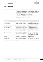
Page 33: ...t match the actual hardware regis try FS communication error Error during FS communication Change faulty module Bus termination error There is no terminating plate or there is a bad contact with the m...

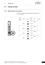
Page 34: ...l pilz gmbh pilz de 7 2 7 2 Display elements 7200 Display elements 7 Anzeige Legende 2x Key 7 2 1 Display elements for module diagnostics Display elements for module diagnostics 7 BA_Anzeige LED Err T...

Page 35: ...Display elements for input status 7 BA_Anzeige LED 4DI Each input is assigned an LED for displaying the input status LEDs 11 21 14 and 24 LED Key Descrip tion Colour Status Signal Input Terminal 11 0...

Page 36: ...7 Operation Pilz GmbH Co KG Felix Wankel Stra e 2 73760 Ostfildern Germany Telephone 49 711 3409 0 Telefax 49 711 3409 133 E Mail pilz gmbh pilz de 7 4...

Page 37: ...5 4 V Module s current consumption 23 mA Module s power consumption 0 12 W Periphery s supply voltage periphery supply Voltage range 16 8 30 0 V Module s current consumption with no load 8 mA Module s...

Page 38: ...in accordance with EN 60068 2 64 T type Frequency 5 500 Hz T type Max acceleration 1 9grms T type Shock stress EN 60068 2 27 base type T type 15g base type T type 11 ms base type T type EN 60068 2 29...

Page 39: ...cabinet IP51 R type Housing IP20 R type Terminals IP20 R type Airgap creepage in accordance with EN 50124 1 R type Overvoltage category OV2 R type Pollution degree PD1 R type Supply interruptions in...

Page 40: ...crew terminals T type 314 600 PSSu BP 1 8C Base module without C rail with cage clamp terminals 312 601 PSSu BP 1 8C T Base module without C rail with cage clamp terminals T type 314 601 PSSu BP 1 12S...

Page 41: ...or contact our headquarters InduraNET p Pilz PIT PMCprotego PMI PNOZ Primo PSEN PSS PVIS SafetyBUS p SafetyEYE SafetyNET p the spirit of safety are registered and protected trademarks of Pilz GmbH Co...

Reviews: