Pilz PSEN cs5.11 M12/8 Operating Manual Download Page 18

PSEN cs5.11 M12/8

Operating Manual PSEN cs5.11 M12/8
1003421-EN-06

18

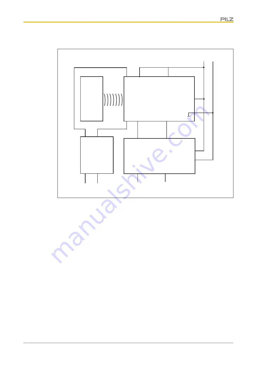
Connection diagram, single connection with SDD

S21

S11

24 V 0 V

A1

A2

12

22
I2 (FS)

I1 (FS)

FS: Failsafe

A1
A2

Y1

Y32

Rx

Tx

Actuator

Safety switch

Evaluation device

Fieldbus module

Summary of Contents for PSEN cs5.11 M12/8

Page 1: ...PSEN cs5 11 M12 8 Operating Manual 1003421 EN 06 PSEN sensor technology...

Page 2: ...nta tion will be gratefully received Source code from third party manufacturers or open source software has been used for some components The relevant licence information is available on the Internet...

Page 3: ...y 8 Unit features 9 Function description 9 Safety Device Diagnostics 10 Operating distances 11 Lateral and vertical offset 13 Wiring 15 Connection to evaluation devices 16 Single connection 17 Series...

Page 4: ...Contents Operating Manual PSEN cs5 11 M12 8 1003421 EN 06 4 Order reference 34 System 34 Accessories 34 EC declaration of conformity 36...

Page 5: ...y important is identified as follows DANGER This warning must be heeded It warns of a hazardous situation that poses an immediate threat of serious injury and death and indicates preventive measures t...

Page 6: ...l Low type 4 The safety switch may only be used with the corresponding actuator PSEN cs5 11 M12 The safety level PL e Cat 4 SIL CL 3 is only achieved if the safety outputs use 2 channel processing The...

Page 7: ...junction for example PSEN ix2 F4 code PSEN ix2 F8 code PDP67 F 4 code PSEN Y junction M12 sensor PSEN Y junction M12 cable You will need to be conversant with the information in these documents in ord...

Page 8: ...cemakers or implanted defibrillators The magnetic field of the safety switch may cause malfunctions of pace makers or implanted defibrillators People with a pacemaker or implanted defibrillators must...

Page 9: ...ult 1 actuation direction with 3 approach directions see Explanation of markings 11 Square marking The guaranteed safe operating distances for the specified selections only apply when the actuator app...

Page 10: ...ostic input Y1 is automatically activ ated and data is read If no fieldbus module of the SDD is used the diagnostic input Y1 is not used Signal output diagnostic output Y32 The status of the actuator...

Page 11: ...ld bus module for simple wiring Information is passed on via the fieldbus module directly to the network Mappings of the signal outputs to the sensor are automated by the SDD This prevents wiring erro...

Page 12: ...06 12 On Off Typical course of change in the holding force as the distance from the switch to the actuator increases with frontal approach 0 5 10 15 20 25 30 35 0 5 10 15 20 25 holding force N distanc...

Page 13: ...fset when aligning to the triangle marking Actuator aligned to the square marking on the switch 1 2 3 4 4 5 6 4 0 14 12 8 4 0 12 8 4 8 4 0 12 14 7 4 4 Legend 1 Hysteresis 2 Typical operating distance...

Page 14: ...triangle marking Actuator aligned to the square marking on the switch 4 5 7 8 1 3 2 8 4 0 12 8 4 0 12 8 4 12 16 8 4 0 12 16 16 16 6 Legend 1 Hysteresis 2 Typical operating distance SO 3 Typical releas...

Page 15: ...ge to the safety switch must be protected with a 2 A to 4 A quick acting fuse Ensure the wiring and EMC requirements of EN 60204 1 are met When connecting in series consider the requirements of manipu...

Page 16: ...gnals are evaluated through 2 channels with feasibility monitoring Please note Information given in the Technical details 30 must be followed The use of Safety Device Diagnostics is described in the S...

Page 17: ...PSEN cs5 11 M12 8 Operating Manual PSEN cs5 11 M12 8 1003421 EN 06 17 Single connection Connection diagram single connection without SDD Actuator Receiver Evaluation device...

Page 18: ...ating Manual PSEN cs5 11 M12 8 1003421 EN 06 18 Connection diagram single connection with SDD S21 S11 24 V 0 V A1 A2 12 22 I2 FS I1 FS FS Failsafe A1 A2 Y1 Y32 Rx Tx Actuator Safety switch Evaluation...

Page 19: ...e maximum delay or risk time permitted by the application Ensure there is sufficient supply voltage taking inrush currents and fusing into considera tion CAUTION Extension of delay on de energisation...

Page 20: ...N cs5 11 M12 8 Operating Manual PSEN cs5 11 M12 8 1003421 EN 06 20 Connection diagram series connection without SDD Actuator Actuator Control system Evaluation device Receiver Receiver Receiver Actuat...

Page 21: ...ction diagram series connection with SDD S11 S21 24 V 0 V A1 A2 12 22 I1 FS I2 FS FS Failsafe ST Standard S11 S21 S11 S21 12 22 12 22 A1 A2 A1 A2 Y1 Y1 Y1 Y32 Y32 Y32 Tx Rx Actuator Safety switch Eval...

Page 22: ...switch type 3 PSS for safety gate monitoring with standard function block SB064 SB066 or FS_Safety Gate The correct connection to the respective evaluation device is described in the operating manual...

Page 23: ...8 PNOZmulti 0 V 24 V PSENcode I2 A1 A2 I0 I1 A1 A2 Y32 Y1 S11 S21 12 22 1 2 3 4 5 6 7 8 Rx Tx PNOZmulti 0 V 24 V PSENcode Fieldbus module Without SDD With SDD Legend I0 Input OSSD I1 Input OSSD I2 Sig...

Page 24: ...the information provided under Technical details 30 The distance between two safety switches must be maintained see Technical details 30 The distance can be undershot in certain application cases see...

Page 25: ...EN 06 25 4 4 3 2 1 1 4 4 3 2 1 1 Fig Seals 1 4 seals for actuators 2 2 seals for actuators 3 2 seals for actuators 4 2 seals for switches and 2 seals for actuators 4 DEVICE SAFETY GATE INPUT DEVICE SA...

Page 26: ...actuator with the triangle marking points towards the triangle mark ing on the sensor 5 Do not fully tighten the second screw on the actuator 6 Align the safety switch and tighten the screws 7 Align...

Page 27: ...for operation Safety Gate yellow Actuator is within the response range Off Actuator is outside the response range Input yellow Both safety inputs are high Off Both safety inputs are low Error display...

Page 28: ...tus Display of last status Outputs in fault con dition Check the outputs and switch the voltage off and then on again green yellow Display not definitive Wrong actuator Use the actuator PSEN cs5 11 M1...

Page 29: ...PSEN cs5 11 M12 8 Operating Manual PSEN cs5 11 M12 8 1003421 EN 06 29 Actuator 18 22 2 7 5 4 5 4 8 3 90 22 90 19 7 5 9 5 Legend 1 Square marking 2 Triangle marking 3 LEDs 4 Semicircle marking...

Page 30: ...DC 1 W Max switching frequency 3 Hz Max cable capacitance at the safety outputs No load PNOZ with relay contacts 40 nF PNOZmulti PNOZelog PSS 40 nF Max inrush current impulse Current pulse A1 0 5 A N...

Page 31: ...8 2 14 Temperature range 25 70 C Max at max operating height 60 C Max at max operating height 2000 m 70 C Storage temperature In accordance with the standard EN 60068 2 1 2 Temperature range 40 85 C C...

Page 32: ...distance Sar 20 mm Typical operating distance So 11 mm Typical release distance Sr 14 mm Typical hysteresis 2 mm Min distance between safety switches 250 mm Sensor flush installation in accordance wit...

Page 33: ...must accept any interference received including interference that may cause undesired operation Changes or modifications made to this product not expressly approved by Pilz may void the FCC authorizat...

Page 34: ...10 PSEN mag cs bracket straight Mounting aid 532 111 PSEN screw M4x20 10pcs Safety screws made from stainless steel with one way slot 540 313 PSEN screw M4x26 10pcs Safety screws made from stainless s...

Page 35: ...8 pin socket 540 337 PSEN Y junction M12 M12 M12 PIGTAIL M12 8 pin socket M12 8 pin pin M12 8 pin socket 540 338 PDP67 F 4 code Decentralised passive junction 773 603 PDP67 F 4 code VA Decentralised p...

Page 36: ...he requirements of the following directives of the European Parliament and of the Council 2006 42 EC on machines 2014 53 EC on radio equipment The complete EC Declaration of Conformity is available on...

Page 37: ...etyNET p THE SPIRIT OF SAFETY are registered and protected trademarks of Pilz GmbH Co KG in some countries We would point out that product features may vary from the details stated in this document de...

Reviews: