background image


The Best of 

German 

Engineering

Partner of:

Support

Technical support is available from Pilz round the clock. 

Americas

Brazil

+55 11 97569-2804

Canada

+1 888-315-PILZ (315-7459)

Mexico

+52 55 5572 1300

USA (toll-free)

+1 877-PILZUSA (745-9872)

Asia

China

+86 21 60880878-216 

Japan

+81 45 471-2281

South Korea

+82 31 450 0680

Australia

+61 3 95446300

Europe

Austria

+43 1 7986263-0

Belgium, Luxembourg

+32 9 3217575

France

+33 3 88104000

Germany

+49 711 3409-444

Ireland

+353 21 4804983

Italy

+39 0362 1826711

Scandinavia

+45 74436332

Spain

+34 938497433

Switzerland

+41 62 88979-30

The Netherlands

+31 347 320477

Turkey

+90 216 5775552

United Kingdom

+44 1536 462203

You can reach our  
international hotline on:  

+49 711 3409-444  
[email protected]

CMSE

®

, Indur

aNET p

®

, P

AS4000

®

, P

AScal

®

, P

ASconfig

®

, P

ilz

®

, PIT

®

, PLID

®

, PMCprimo

®

, PMCpr

ot

ego

®

, PMCt

endo

®

, PMD

®

, PMI

®

, PNO

Z

®

, P

rimo

®

, PSEN

®

, PSS

®

, PVIS

®

, SafetyBUS p

®

,  

SafetyEYE

®

, SafetyNET p

®

, T

h

SPI

r

IT

 O

SA

fET

Y

®

 ar

e r

egist

er

ed and pr

ot

ect

ed tr

ademarks of P

ilz Gmb

h

 & Co. K

G in some countries. W

e would point out that pr

oduct featur

es may var


from the details stat

ed in this document, depending on the status at the time of publication and the scope of the equipment. W

e accept no r

esponsibility for the validity, accur

acy


and entir

ety of the t

ext and gr

aphics pr

esent

ed in this information. Please contact our T

echnical Suppor

t if you have any questions.

Pilz develops environmentally-friendly products using  
ecological materials and energy-saving technologies.  
Offices and production facilities are ecologically designed, 
environmentally-aware and energy-saving. So Pilz offers 
sustainability, plus the security of using energy-efficient  
products and environmentally-friendly solutions.

Pilz Gmbh & Co. KG 
felix-Wankel-Straße 2 
73760 Ostfildern, Germany
Tel.: +49 711 3409-0 
fax: +49 711 3409-133 
[email protected]
www.pilz.com

100XXXX-DE-0X

0-0-1-3-000, 2015-00 P

rint

ed in Germany

© P

ilz Gmb

h

 & Co. K

G, 2015

1002265-EN-02, 2016-05 Printed in Germany

© Pilz GmbH & Co. KG, 2015

Front cover

Summary of Contents for PNOZmulti

Page 1: ...PNOZmulti Installation Manual Installation Manual 1002265 EN 02 Configurable control systems PNOZmulti 2 Configurable compact control systems PNOZmulti Mini Configurable safety systems PNOZmulti...

Page 2: ...umentation will be gratefully received Source code from third party manufacturers or open source software has been used for some components The relevant licence information is available on the Interne...

Page 3: ...liance of an installation 14 Section 4 Installation 16 4 1 Control cabinet installation 16 4 1 1 General installation guidelines 16 4 1 1 1 Positioning of units 16 4 1 2 Mounting distances 17 4 2 Inst...

Page 4: ...dules 27 5 10 Connection example analogue input module and speed monitor 29 5 11 Fieldbus modules 31 5 12 Link modules 31 5 13 Cascading 32 5 13 1 System requirements 33 5 13 2 Series connection 33 5...

Page 5: ...e small control systems PNOZmulti Configurable control systems PNOZmulti 2 Configurable compact control systems PNOZmulti Mini Configurable safety systems PNOZmulti The documentation is valid until ne...

Page 6: ...a situation in which the product or devices could be dam aged and also provides information on preventive measures that can be taken It also highlights areas within the text that are of particular imp...

Page 7: ...issioned operated maintained and decommissioned by competent persons A competent person is someone who because of their training experience and current pro fessional activity has the specialist knowle...

Page 8: ...ol systems should be installed in an enclosure e g control cabinet The control cabinet must conform to the protection class required for the environment Please refer to the technical details of the re...

Page 9: ...Safety Installation Manual PNOZmulti Installation Manual 1002265 EN 02 9 The base units PNOZ m B1 have a USB memory for saving and downloading projects...

Page 10: ...ce and sink of interference have common cable connec tions The common cable presents complex resistances inducing potential differences Typical sources of interference are switches relays running moto...

Page 11: ...plies and earth the 0 V mains at a single point or ensure that measures are in place to monitor for earth faults Earthed supply voltages offer the best noise immunity The connection of the 0 V supply...

Page 12: ...rences can occur if the devices are connected to different earth or ground connections Even cable shields that are connected at either end and have different earth connections can cause potential diff...

Page 13: ...without making a break in the cable Use metal cable clamps which cover the shield over a wide surface area Route the shield as far as the units but do not connect it to the units Digital inputs and ou...

Page 14: ...er EMC characteristics of indi vidual units all units tested once installed Test EMC characteristics under operating con ditions e g while hand held radios are in use or HF frequency generators are cl...

Page 15: ...2 9 1995 EN 60950 1 2006 A11 2009 or EN 50178 10 97 Mains in accordance with TN S system This guarantees that there is no connection between the neutral conductor and protective conductor within the m...

Page 16: ...s Note the relevant standards when wiring the control cabinet For example DIN EN 61439 1 VDE 0660 600 1 2012 06 Low voltage switchgear and control gear assemblies Part 1 General rules DIN EN 61439 2 V...

Page 17: ...stated for the mounting distances are minimum specifications The ambient temperature in the control cabinet must not exceed the figure stated in the technical details Air conditioning may otherwise b...

Page 18: ...ft hand side of the base unit Terminator Termination Link 4 2 2 Connect the base unit and expansion modules The modules are linked via jumpers There are 2 pin connectors on the rear of the base unit M...

Page 19: ...3 Install the control system PNOZmulti Mini 4 3 1 Install base unit without expansion module Make sure that the terminators are inserted on the top left and right of the unit Left Black yellow termin...

Page 20: ...ling the units on the mounting rail connect the base unit to the expansion module using the jumper supplied Fit the appropriate terminator to the unconnected interfaces on the base unit and ex pansion...

Page 21: ...ystem PNOZmulti 2 4 4 1 Install base unit without expansion module Make sure that the terminators are inserted on the top left and right of the unit IM0 IM1 IM2 I6 I5 I4 IM3 I7 I8 I9 I10 I14 I13 I12 I...

Page 22: ...types The modules are linked via jumpers Remove the terminator on the side of the base unit and on the expansion module Install the base unit and expansion modules on the mounting rail in the order c...

Page 23: ...rs located outside the control cabinet Where the cable enters the control cabinet the cable shield must be connected to the earth potential over a wide surface area and with low impedance connect in s...

Page 24: ...be used to dissipate hazardous voltages in the case of a fault The mounting rail must be properly earthed to ensure interference free operation in accord ance with EMC regulations INFORMATION Please...

Page 25: ...ction 2 Stripping length 9 mm Please note Use copper wiring with a temperature stability of 75 C You must comply with the specifications of the cable manufacturer 5 5 Terminals The plug in terminals f...

Page 26: ...for a configurable control system PNOZmulti e g PNOZ m1p with expansion modules L1 L2 L3 N PE TN S Control cabinet Earthing bar Mounting rail 5 V DC 0 V 24 V DC 0 V Functional earth Periphery Sensors...

Page 27: ...eparate power supply isolated from the drive should be used to supply voltage to the sensors INFORMATION The following applies for the speed monitor PNOZ msXp with RJ45 connec tion The shield connecti...

Page 28: ...the min bending radius The cable outlet should be placed face down vertically in order to op timise the connector s contact and stability The adapter cable connection cable should be laid flush so as...

Page 29: ...ng Module 5 10 Connection example analogue input module and speed monitor Please note the following guidelines for connecting the shield Use shielded cable for the input circuit connection cables 6 an...

Page 30: ...Z ms2p Key 1 Control cabinet wall 2 Cable bushing 3 Supply voltage for sensors 4 Connections for analogue inputs and supply voltage for sensors 5 Shield bar 6 Sensor signal lines 7 Shielded terminal 8...

Page 31: ...rminals see Order reference in the operating manuals You can use ready made cable from Pilz to connect the devices Cable properties PNOZ ml1p PNOZ ml1p PNOZ ml2p Decentralised modules PDP67 PNOZ mml1p...

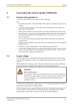
Page 32: ...cess to a logic output and or an input on the connected base unit The base units can be connected in series or a tree structure can be built PNOZelog units may also be included in the network The casc...

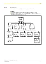
Page 33: ...log Unit 4 5 13 1 System requirements PNOZmulti Configurator from Version 3 0 0 Please contact Pilz if you have an older version 5 13 2 Series connection As many PNOZ m1p base units as necessary may b...

Page 34: ...y be incorporated in parallel on each level PNOZelog units may only be connected to the PNOZmulti units in series Max of one PNOZelog unit is permitted on each level CI CI CO CO PNOZ m1p S36 S35 A2 14...

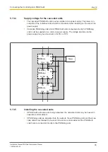
Page 35: ...tly to PNOZelog units must be supplied via a common power supply The voltage tolerance on the power supply may be a maximum of 20 or 10 S36 S35 A2 14 24 A2 PNOZelog CI CI CO CO PNOZ m1p CI CI CO CO PN...

Page 36: ...e following when wiring Cable runs between the connected units PNOZmulti PNOZmulti Max 100 m PNOZelog PNOZmulti cascaded directly Max 10 m Cable material see Technical details Outside the control cabi...

Page 37: ...p the spirit of safety are registered and protected trademarks of Pilz GmbH Co KG in some countries We would point out that product features may vary from the details stated in this document dependin...

Reviews: