


Operation
Operating Manual PNOZ mml2p
1002234-EN-04
19
7
Operation
When the supply voltage is switched on, the PNOZmulti safety system copies the configur-
ation from the chip card.
The LEDs “POWER”, “DIAG”, “FAULT”, “IFAULT” and “OFAULT” will light up on the base
unit.
The PNOZmulti safety system is ready for operation when the "POWER" and "RUN" LEDs
on the base unit and the "READY" LED on the PNOZ mml2p are lit continuously.
7.1
LED indicators
Legend
LED on
LED flashes
LED off
LED
LED status
Meaning
Power
No supply voltage
Gree
n
Supply voltage is present
Ready
Gree
n
The unit is ready for operation
The unit is not ready for operation
Fault
Red External error
Red Internal error
No fault
Traffic
Yel-
low
Connection to a decentralised module avail-
able
Yel-
low
Connection is not available to all decentralised
modules.
No connection to a decentralised module
7.2
Fault detection
The base unit contains information about the
}
Link module (in order, defective, no supply voltage)
}
Status of communication with the decentralised modules (data valid, data invalid)
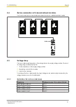
If the connection to a decentralised module is interrupted or there is a major error on the
decentralised module, the inputs on the devices connected to the link module are set to
zero. The base unit remains in a RUN condition.


