background image

PSEN op4H-SL Series

Operating Manual PSEN op4H-SL Series
1004305-EN-01

5

Introduction

Validity of documentation

This documentation is valid for the product PSEN op4H-SL Series. It is valid until new doc-
umentation is published.
This operating manual explains the function and operation, describes the installation and
provides guidelines on how to connect the product.

Using the documentation

This document is intended for instruction. Only install and commission the product if you
have read and understood this document. The document should be retained for future ref-
erence.

Definition of symbols

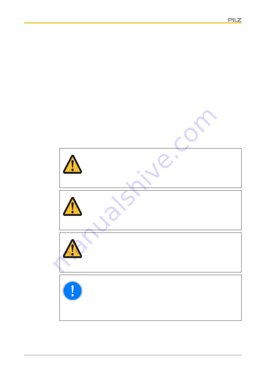
Information that is particularly important is identified as follows:

DANGER!

This warning must be heeded! It warns of a hazardous situation that poses
an immediate threat of serious injury and death and indicates preventive
measures that can be taken.

WARNING!

This warning must be heeded! It warns of a hazardous situation that could
lead to serious injury and death and indicates preventive measures that can
be taken.

CAUTION!

This refers to a hazard that can lead to a less serious or minor injury plus
material damage, and also provides information on preventive measures
that can be taken.

NOTICE

This describes a situation in which the product or devices could be dam-
aged and also provides information on preventive measures that can be
taken. It also highlights areas within the text that are of particular import-
ance.

Summary of Contents for 631120

Page 1: ...PSEN op4H SL Series Operating Manual 1004305 EN 01 PSEN sensor technology...

Page 2: ...umentation will be gratefully received Source code from third party manufacturers or open source software has been used for some components The relevant licence information is available on the Interne...

Page 3: ...on 14 Protected field perimeters 14 Ambient conditions 14 Distance from reflective surfaces 15 Minimum distance between parallel aligned safety light grids 17 Installation of several adjacent safety l...

Page 4: ...ion 38 Display elements 38 Status information 39 Safety light grid restart 40 Malfunction 41 Regular checks and maintenance 41 Checks 41 Regular check 41 Check after plant machine modification 41 Main...

Page 5: ...that is particularly important is identified as follows DANGER This warning must be heeded It warns of a hazardous situation that poses an immediate threat of serious injury and death and indicates pr...

Page 6: ...ivers Connection to evaluation devices see System connection 35 with 5 pin M12 one sided connector and open cable end connection to clamping sleeves EDM when connected to a relay with positive guided...

Page 7: ...4 4 2 1 3 40 7 6 6 6 2 1 6 3 Fig Views of safety light grids with connection cable Attachment using O bracket C bracket or L bracket Legend 1 Protected field height 2 Connection cable M12 connector 3...

Page 8: ...Safety light grids of the PSEN op4H SL Series are electrosensitive protective equipment of the 4 They are used to protect personnel and systems The safety light grids are designed for securing hazard...

Page 9: ...med improper use in particular Any component technical or electrical modification to the product Use of the product outside the areas described in this manual Use of the product outside the technical...

Page 10: ...ty and liability will be rendered invalid if The product was used contrary to the purpose for which it is intended Damage can be attributed to not having followed the guidelines in the manual Operatin...

Page 11: ...assigned to the transmitter and receiver on the LED side The transmitter and receiver are optically synchronised and therefore need not be directly connected to each other Information about the operat...

Page 12: ...y light grid can be monitored External Device Monitoring EDM also known as feedback loop monitoring EDM only needs to be activated if the contactors are controlled directly A test is performed to see...

Page 13: ...o this first safety light grid The first safety light grid is the master unit the safety light grid connected to the master unit is the slave unit Max 2 slave units to one master unit Max overall leng...

Page 14: ...the hazardous area in mm s K 1600 mm s when S 500 mm K 2000 mm s when S 500 mm t1 Response time of the safety light grid in seconds Time it takes for the signal at the OSSD output on the safety light...

Page 15: ...grid avoid the development of smoke mist or dust that would reduce the grid s operating range Distance from reflective surfaces If there are reflective surfaces near the beams emitted from the safety...

Page 16: ...rface 7 Distance between transmitter and receiver working distance 8 Hazardous area The minimum distance D depends on two factors Working distance between transmitter and receiver the maximum opening...

Page 17: ...ce D Minimum distance between parallel aligned safety light grids Please note Safety light grids that are installed so as to be parallel and aligned must have a minimum spacing corresponding to the in...

Page 18: ...e orientation opposite to 2 4 Receiver 5 Transmitter Use of deviating mirrors Danger zones with different but adjacent access sides can be monitored using a safety light grid in conjunction with devia...

Page 19: ...id Minimum distance for cascaded safety light grids When safety light grids are cascaded with two slave units be sure to maintain the minimum distance between the master unit and slave unit 2 Width of...

Page 20: ...004305 EN 01 20 Installation using O brackets 2 1 Legend 1 Reduced resolution of 40 mm at the ends of the safety light grid 2 O brackets Installation using L brackets 2 1 Legend 1 Reduced resolution o...

Page 21: ...resolution of 18 mm at the ends of the safety light grid Use C brackets or L brackets when safety light grids are arranged at right angles 1 Legend 1 C or L brackets Installation Please note The opti...

Page 22: ...mmend 3 C brackets Install the third C bracket in the same way in the middle between the 2 C brackets as additional support 1 Make two drill holes in the mounting surface as shown 1 and install the C...

Page 23: ...of the safety light grid Legend 1 Fixing screw 2 Coding lug for the connection end of the safety light grid For safety light grids with a protected field height over 600 mm and strong vibration we re...

Page 24: ...tected field height Distance of holes for attaching the O brackets 150 162 2 210 222 1 270 282 0 300 312 0 330 341 9 360 371 9 390 401 7 420 431 7 450 461 7 480 491 6 510 521 6 540 551 5 570 581 5 600...

Page 25: ...1004305 EN 01 25 1 2 3 4 5 Legend 1 Mounting surface 2 PSEN op4H SL Series 3 O bracket Non connection end of safety light grid 4 O bracket Connection end of safety light grid 5 Distance between the ho...

Page 26: ...ted hole washers 1 Make two drill holes 1 in the mounting surface per L bracket at a distance corres ponding to the length of the safety light grid 2 2 Attach the vertical section of both L brackets 3...

Page 27: ...face 2 Distance between the drill holes Height of the safety light grid see Technical details 43 3 Vertical section of L bracket 4 Horizontal section of L bracket 5 Clamp the transmitter receiver into...

Page 28: ...acket at the connection end as shown 1 and install the vertical section and horizontal section of the L bracket 2 Tighten all screws to 1 2 Nm 2 Make two drill holes in the mounting surface as shown 1...

Page 29: ...r as it will go 6 M3 screw to position the clamping jaw of the C bracket 7 Attach the horizontal section of the L bracket to the vertical section using M3 screws Cascaded safety light grid Transmitter...

Page 30: ...lamps for connection to the evaluation device must be kept in a locked control cabinet This prevents unauthorised modifications Ensure compliance with permissible cable bending radii see Technical det...

Page 31: ...ed black Wiring for manual restart 5 pin connector on the transmit ter PIN Assignment Cable colour 5 3 1 24 V Restart 0 V Restart Selection 2 4 n c n c 1 24 VDC brown 3 0 VDC blue 2 Leave Pin 2 unconn...

Page 32: ...SD 1 white 5 Pin 5 controlled via N C contact of the positive guided relay grey Earthing the safety light grid Please note Connect the 0 V connections on all the 24 V power supplies and earth the 0 V...

Page 33: ...female socket 1 Install the master unit and slave unit s See Installation 22 2 Loosen the screws 1 on the cover of the cascading adapter and remove the cover 1 Legend 1 Fixing screws on the cover of...

Page 34: ...brackets on the profile and move within the slot L bracket Vertical Remove the safety light grid and brackets completely and drill new holes Horizontal Remove safety light grid from bracket loosen the...

Page 35: ...yel low red green Synchronisation of first and last light beams One or more light beams are interrupted yel low yel low green green Synchronisation of first and last light beams Weak signal strength P...

Page 36: ...device according to the specifica tions in the selected evaluation device s operating manual 5 3 1 2 4 5 3 1 0 V 24 V 24 V 0 V EDM OSSD 1 OSSD 2 24 V Restart 0 V 24 V 0 V Restart Selection 2 4 n c Re...

Page 37: ...field 2 Place the test rod at rest in a position in the protected field that is considered critical for the safety assessment results 1 Legend 1 Test rod Check ambient conditions and installation Cor...

Page 38: ...in Maintaining the safety distance No intense or flashing light sources in the vicinity There may be no especially intense or flashing light sources in the vicinity of the safety light grid Ambient c...

Page 39: ...then on again If the error persists please contact Pilz yel low red green Error in the synchronisation of the light beams Check the ambient conditions and the wir ing Switch the safety light grid off...

Page 40: ...r Check the ambient conditions and the wir ing Switch the safety light grid off and then on again yel low green Error in the synchronisation of the light beams Check the ambient conditions and the wir...

Page 41: ...he safety light grid Dirty front panel Clean the front panel 42 In a particularly dirty environment front panel cleanliness should be checked more frequently Check the tightness of the safety light gr...

Page 42: ...tenance CAUTION Improper cleaning agents can damage the safety light grid and lead to mal functions Moist cotton cloths should be used for cleaning Avoid using Alcohol Solvents Cloths made of wool Cl...

Page 43: ...eceiver 4 2 W 4 2 W 4 2 W Max power consumption transmitter 1 6 W 1 6 W 1 6 W Protection class 3 3 3 Optical data 631120 631121 631122 Opening angle 2 5 2 5 deg 2 5 2 5 deg 2 5 2 5 deg Used wavelength...

Page 44: ...0 631121 631122 Cable length L1 0 2 m 0 2 m 0 2 m Min bending radius fixed permanently K1 1 x 1 x 1 x Min bending radius fixed permanently cascading cable 1 x 1 x 1 x Cable insulation material K1 PVC...

Page 45: ...ceiver 4 2 W 4 2 W 4 2 W Max power consumption transmitter 1 6 W 1 6 W 1 6 W Protection class 3 3 3 Optical data 631123 631124 631125 Opening angle 2 5 2 5 deg 2 5 2 5 deg 2 5 2 5 deg Used wavelength...

Page 46: ...631124 631125 Cable length L1 0 2 m 0 2 m 0 2 m Min bending radius fixed permanently K1 1 x 1 x 1 x Min bending radius fixed permanently cascading cable 1 x 1 x 1 x Cable insulation material K1 PVC P...

Page 47: ...transmit ter 1 6 W 1 6 W Protection class 3 3 Optical data 631126 631127 Opening angle 2 5 2 5 deg 2 5 2 5 deg Used wavelength range 850 nm 850 nm Semiconductor outputs 631126 631127 OSSD safety outpu...

Page 48: ...rman ently cascading cable 1 x 1 x Cable insulation material K1 PVC PVC Connection type Receiver M12 5 pin male connector M12 5 pin male connector Transmitter M12 5 pin male connector M12 5 pin male c...

Page 49: ...grid Product type Features Order no PSEN op4H SL 24 015 1 Safety light grid for hand protection protected field height of 150 mm 631 120 PSEN op4H SL 24 030 1 Safety light grid for hand protection pro...

Page 50: ...98 Cascading Product type Connection 1 Connection 2 Length Order No PSEN op SL cascading M12 5 pin socket 5 pin cascading ad apter 0 1 m 631 183 0 5 m 631 184 1 m 631 185 Test object Product type Feat...

Page 51: ...nd store it with the machine docu mentation for reference No Action OK NOT OK Notes 1 Check the category standards Does the category of the safety light grid match the category required for the plant...

Page 52: ...ons to the safety light grid wired correctly 7 Check the effectiveness of the safety light grid during the hazardous move ment Is the safety light grid effective throughout the whole of the plant mach...

Page 53: ...of manufacture A January B February C March D April E May F June G July H August I September L October M November N December Consecutive number within the month EC declaration of conformity This produ...

Reviews: