Installation
Operating Manual PSSu E S PD-D
21975-EN-05
18
5.3.1
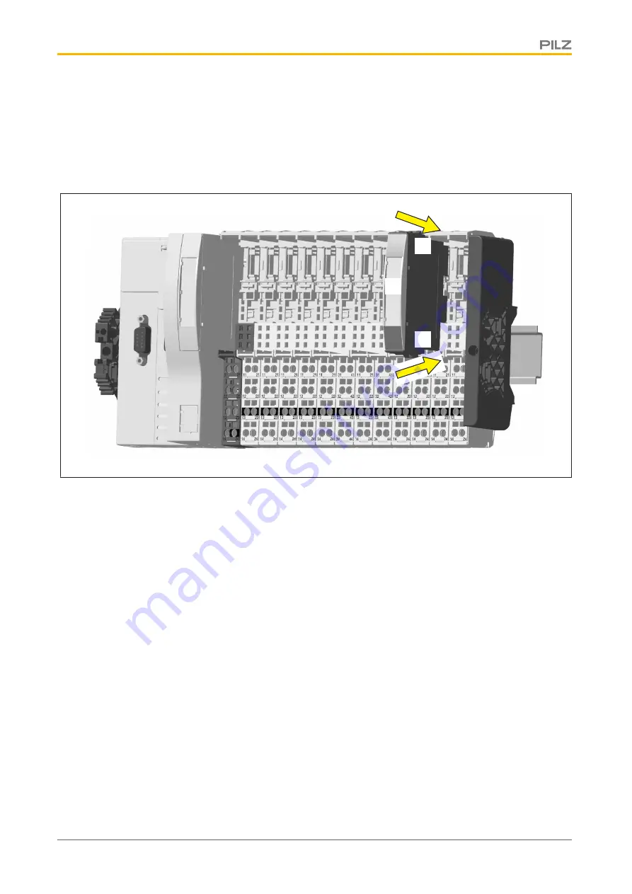
Inserting an electronic module
Procedure:
}
The electronic module must audibly lock into position [1].
}
Mark the electronic module using the labelling strips [2].
Schematic representation:
[2]
[1]
[1]


