background image


                                                   Component Maintenance Manual


EFFECTIVITY:  ALL 


21-00-22

Page 

2001


JULY 21, 2011

SCHEMATIC AND WIRING DIAGRAMS 

21-00-22-99-801 

4.0 

R12 AIR CONDITIONING SYSTEM SCHEMATIC AND WIRING DIAGRAMS 

SUBTASK 21-00-22-99-001 

4.1 

R12 Refrigerant Flow Schematic: 

4.1.1 

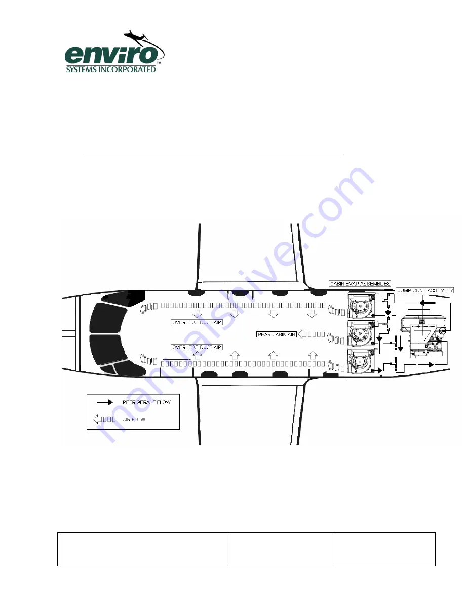
The following schematic shows an air conditioning system and its associated components 
as well as the flow of the R12 refrigerant. 

Figure 2 R12 Refrigerant Flow Schematic 


Summary of Contents for PC-12

Page 1: ...NC ORIGINAL ISSUE DECEMBER 28 2007 21 00 22 JULY 21 2011 OPERATING SERVICING AND COMPONENT MAINTENANCE MANUAL WITH ILLUSTRATED PARTS LIST PILATUS PC12 R 12 AIR CONDITIONING SYSTEM COMPONENTS 1 COMPRES...

Page 2: ...nt Figures 4 and 5 and references to those Figures Revise Note above Table 3 to remove reference to Figure 3 Wiring Schematic 9 19 08 BH 3 Change and label Table 3 5 3 6 to corrected schedule hours an...

Page 3: ...Component Maintenance Manual EFFECTIVITY ALL 21 00 22 Record of Temporary Revisions Page 2 JULY 21 2011 RECORD OF TEMPORARY REVISIONS REV DESCRIPTION OF CHANGE DATE APPROVAL...

Page 4: ...Component Maintenance Manual EFFECTIVITY ALL 21 00 22 List of Service Bulletins Page 3 JULY 21 2011 LIST OF SERVICE BULLETINS SERVICE BULLETIN DESCRIPTION DATE RELEASED...

Page 5: ...ce Manual EFFECTIVITY ALL 21 00 22 List of Effective Pages Page 4 JULY 21 2011 LIST OF EFFECTIVE PAGES CHAPTER SECTION PAGE DATE CHAPTER SECTION PAGE DATE All All 12 28 07 All All 5 5 08 All All 9 19...

Page 6: ...ISOLATION 1001 3 1 General 1001 3 2 Compressor Condenser Module Testing Procedures 1001 3 3 Evaporator Module Testing Procedures 1001 3 4 System Leak Check Testing Procedure 1002 3 5 Fault Isolation...

Page 7: ...NT ILLUSTRATED PARTS LISTING 10001 11 1 Introduction 10001 SPECIAL PROCEDURES 11001 12 0 SPECIAL PRODECURES 11001 12 1 Expansion Valve Alignment 11001 12 2 Balancing Multiple Evaporators 11002 12 3 Mo...

Page 8: ...ompressor Condenser Module Assembly 1250900 4 Details 10003 Figure 10001 Compressor Condenser Module Assembly 1250900 4 Details Cont 10004 Figure 10002 Evaporator Module Assembly 1250200 42 L 43 C R 1...

Page 9: ...ystems tries to cover all conceivable issues that may arise there may be issues that are not covered in this manual In these cases please call Enviro Systems customer service 1 1 4 This manual uses th...

Page 10: ...99F 002 1 2 Acronyms Abbreviations and Symbols CMM Component Maintenance Manual ATA Air Transport Association MTOSS Maintenance Task Oriented Support System EDP Electronic Data Processing IPL Illustra...

Page 11: ...NECTIONS RECEIVER DRYER SUCTION DISCHARGE PORT 132 156 IN LBS 7 8 14 PLUMBING CONNECTIONS COMPRESSOR SUCTION PORT 252 324 IN LBS 16 PLUMBING CONNECTIONS COMPRESSOR DISCHARGE PORT 180 240 IN LBS 7 16 2...

Page 12: ...id manufacturer s warranty 2 1 3 Inspections servicing and or maintenance schedules are presented in the following sections This will ensure component and or system reliability and performance are mai...

Page 13: ...ejected to the outside through the system condenser When the system is turned on the electric motor drives the R12 compressor at a constant speed and capacity which compresses the R12 refrigerant gas...

Page 14: ...mpressor drive motor has a double ended shaft and operates on 27 5 VDC power with a rated current draw of 115 AMPS max One output shaft drives the R12 compressor and the other end drives the motor coo...

Page 15: ...E SWITCH The binary pressure switch performs two major functions The first function prevents the R12 compressor from operating if the system charge is lost or the ambient temperature is too low The se...

Page 16: ...superior strength and durability 2 3 5 4 BLOWER SCROLL The blower scroll is constructed of high impact fire retardant self extinguishing and corrosion resistant lightweight polycarbonate material It...

Page 17: ...access to the Compressor Condenser Module refer to the aircraft maintenance manual for removal of access panels and other hardware that might need to be removed Verify that these components are opera...

Page 18: ...he expansion valve s might need aligning Refer to Special Procedures Section 12 for Expansion Valve Alignment procedures SUBTASK 21 00 22 70 003 3 4 System Leak Check Testing Procedure 3 4 1 A leak ch...

Page 19: ...install quick connect push on firmly until locked a clicking sound is heard Hold the grip ring and pull to remove quick connect fittings 3 4 3 8 Connect yellow charging hose to a regulated dry nitroge...

Page 20: ...WLY TO ASSURE COMPRESSOR OIL IS NOT VENTED WITH THE NITROGEN DO NOT LET AIR ENTER THE SYSTEM 3 4 3 16 After leak check is finished and system integrity is sound turn off nitrogen source disconnect yel...

Page 21: ...m Will Not Operate 1 Air conditioner breaker off 1 Turn on 2 Air conditioner breaker failed 2 Replace 3 Air conditioner mode switch failed 3 Replace 4 Relay s failed 4 Replace 5 Failed pressure switch...

Page 22: ...gged 13 Remove Debris 14 Excessive moisture in system 14 Replace receiver dryer 15 Excessive oil in system 15 Drain excessive oil D Evaporator Noisy 1 Blower wheel out of round 1 Replace 2 Blower whee...

Page 23: ...or replace 2 Mode switch failed 2 Replace 3 Fan speed switch failed 3 Replace 4 Seized motor 4 Replace 5 Blower wheel failed 5 Replace 6 Blocked air ducts 6 Remove debris 7 Aircraft power not on 7 En...

Page 24: ...00 22 99 801 4 0 R12 AIR CONDITIONING SYSTEM SCHEMATIC AND WIRING DIAGRAMS SUBTASK 21 00 22 99 001 4 1 R12 Refrigerant Flow Schematic 4 1 1 The following schematic shows an air conditioning system and...

Page 25: ...mbly should only be performed to the extent necessary to access any faulty subassembly 5 1 1 Gain access to the system component or components requiring disassembly refer to the aircraft maintenance m...

Page 26: ...electrical wiring to binary pressure switch 5 2 1 3 Disconnect refrigerant plumbing connection from receiver dryer inlet port 5 2 1 4 Disconnect discharge refrigerant line from receiver dryer outlet...

Page 27: ...cap off immediately 5 2 4 3 Remove compressor mounting bolts and washers 5 2 4 4 Carefully lift compressor from mounting bracket 5 2 5 Removal of Drive Motor 5 2 5 1 Remove belt cover drive pulley and...

Page 28: ...ardware and carefully slide relay from assembly 5 2 9 Removal of Hour Meter 5 2 9 1 Disconnect electrical terminals from hour meter and mark for later identification 5 2 9 2 Remove attaching screws wa...

Page 29: ...tor Module Assembly 5 3 1 1 Refer to aircraft maintenance manual for removal of Evaporator Module Assembly 5 3 2 Removal of Expansion Valve 5 3 2 1 Disconnect refrigerant plumbing lines and cap off im...

Page 30: ...VES AND PROTECTIVE CLOTHING WHEN USING CERTAIN CLEANING SOLVENTS AND OR CHEMICALS INGESTION OF CERTAIN SOLVENTS AND OR CHEMICALS CAN CAUSE SERIOUS INJURY OR EVEN DEATH WHENEVER CLEANING PROCEDURES INV...

Page 31: ...e the Condenser Coil will become dirty and require general cleaning It is essential that the assembly remain clean to ensure proper operation and optimal performance The coil fins will over time becom...

Page 32: ...irt dust and other foreign matter If air filter shows signs of deterioration replace filter refer to Disassembly Section 5 and Assembly Section 9 6 3 1 3 EVAPORATOR HOUSING ASSEMBLY The components tha...

Page 33: ...as required Inspect belt cover for cracks or other damage 500 Compressor shaft seal Visually inspect for leaks excessive oil spray 500 Condenser outlet and fan shrouds Visually inspect condenser outle...

Page 34: ...Component Maintenance Manual EFFECTIVITY ALL 21 00 35 Page 5002 JUNE 15 2011 Figure 4 Commutator In Excellent Condition...

Page 35: ...Component Maintenance Manual EFFECTIVITY ALL 21 00 35 Page 5003 JUNE 15 2011 Figure 5 Commutator In Serviceable Condition...

Page 36: ...Component Maintenance Manual EFFECTIVITY ALL 21 00 38 Page 5004 MAY 1 2008 Figure 6 Commutator In Unserviceable Condition...

Page 37: ...n 8 Component Type Inspection Required Times Evaporator Coil Assembly Inspect refrigerant plumbing for leakage Inspect coil fins for cleanliness and damage Inspect cold air ducting for leaking cracks...

Page 38: ...NCE OPERATION THIS INCLUDES NOT ALLOWING THE RECEIVER DRYER TO BE EXPOSED TO ATMOSPHERIC CONDITIONS FOR ANY LENGTH OF TIME ALL PLUMBING LINES SHOULD REMAIN CAPPED WHENEVER POSSIBLE DURING THE SERVICIN...

Page 39: ...EXCESSIVELY WORN THE MOTOR SHOULD BE REPLACED OR REBUILT IF THE DEPTH OF THE MICA UNDERCUT REMAINING ON THE COMMUTATOR IS LESS THAN 020 INCH THE MOTOR SHOULD ALSO BE REPLACED See Illustration 4 3 THR...

Page 40: ...V to cure for a minimum of 24 hours before operating system If the shrouds are cracked or are damaged in any other way they should be replaced Contact ENVIRO Systems customer service to order new comp...

Page 41: ...be removed and replaced refer to aircraft maintenance manual Contact Pilatus Aircraft Customer Service for replacement component 8 3 1 3 BLOWER ASSEMBLY The components that comprise the blower assemb...

Page 42: ...ALVE The expansion valve can over time become damaged and or not operate correctly If the expansion valve shows signs of damage or does not function properly remove and replace refer to Disassembly Se...

Page 43: ...R DRYER MUST BE REPLACED ANY TIME THE VCS PLUMBING IS OPENED FOR MAINTENANCE REFER TO DISASSEMBLY SECTION 5 AND ASSEMBLY SECTION 9 9 1 2 Gain access to the Compressor Condenser Module and Evaporator M...

Page 44: ...ve been tested refer to Testing and Fault Isolation Sect 3 9 2 1 2 Lift brush spring and slide brush into brush rack Verify that brush direction is against commutator 9 2 1 3 Seat new brushes accordin...

Page 45: ...RINGLY TO THREADS STAYING CLEAR OF FIRST 2 3 THREADS 9 2 3 3 Apply a drop of thread sealant to the set screw thread Tighten fan assembly set screws refer to table 1 Section 1 3 for torque specificatio...

Page 46: ...Connect condenser fitting to compressor discharge port and tighten refer to table 1 section 1 3 for torque specifications 9 2 6 Assembly of Drive Belt and Pulley 9 2 6 1 Belt should be tensioned refer...

Page 47: ...otor refer to table 1 section 1 3 for torque specifications 9 2 8 Assembly of Receiver Dryer 9 2 8 1 Carefully slide receiver dryer into mounting clamp and tighten clamp 9 2 8 2 Using a wire brush and...

Page 48: ...nect electrical connections and install boots for protection 9 2 10 Assembly of Hour Meter 9 2 10 1 Carefully slide hour meter into hour meter opening and secure with attaching hardware refer to table...

Page 49: ...RE NOT TO GET REFRIGERANT OIL ON FITTING THREADS 9 3 1 4 Apply thin film of refrigerant oil to expansion valve flare surface and a very small amount to the O rings to prevent damage 9 3 1 5 Connect ex...

Page 50: ...hand tools and socket set Shop vacuum with soft utility brush Vacuum pump air or electric 0 30 in hg Gaseous dry Nitrogen regulated source 0 500 PSIG Reclaim Recycle Cart R12 Robinair model 342000 pre...

Page 51: ...nent Maintenance Manual EFFECTIVITY ALL 21 00 22 Page 9002 JULY 21 2011 Straight Edge Measuring Device Micrometer Scribe or Wire Hook Volt OHM Meter Belt Tensioning Tool T1134610 Spring Scale Wagner F...

Page 52: ...the Compressor Condenser Module and Evaporator Module Assembly to be used during the procedures outlined previously 11 1 3 This IPL includes figure and item numbers to call out specific components Ea...

Page 53: ...Component Maintenance Manual EFFECTIVITY ALL 21 00 22 Figure 10001 Page 10002 JULY 21 2011 Figure 10001 Compressor Condenser Module Assembly 1250900 4...

Page 54: ...2 20C 1250146 5 DRIVE PULLEY 1 30 1250170 FAN BLADE 1 31 28X5 16B SET SCREW 2 32 NAS1149F0463P FLAT WASHER AN960 416 3 33 21FK 624 NUT 1 40A 1250120 COMPRESSOR ASSEMBLY 1 41 AN6 10A BOLT 2 42 21FK 62...

Page 55: ...3 CONDENSER SUPPORT BRACKET 1 111 AN500 A8 6 SCREW 4 112 NAS1149FN832P FLAT WASHER AN960 8 4 113 MS35265 30 SCREW 2 114 NAS1149FN632P FLAT WASHER AN960 6 2 120C 1250703 1 HOUR METER 1 121 AN500 6 6 SC...

Page 56: ...Component Maintenance Manual EFFECTIVITY ALL 21 00 22 Figure 10002 Page 10005 JULY 21 2011 Figure 10002 Evaporator Module Assembly 1250200 42 L 43 C R...

Page 57: ...ASSY 10002 10A 1250218 EXPANSION VALVE 42 1 1250218 1 EXPANSION VALVE 43 1 20B 1250540 11 AIR FILTER 1 21 190940 VELCRO HOOK 2 6 FT 1 22 190911 VELCRO LOOP 2 6 FT 1 30A BLOWER MOTOR N P 40A SHROUD N...

Page 58: ...and discharge pressures as outlined in Table 4 12 1 2 Tools fixtures equipment or consumable items required Small hand tools and socket set Micrometer Scribe or wire hook Volt OHM meter digital Shop...

Page 59: ...the typical values outlined Table 4 the expansion valve must be turned CCW in revolution increments Wait 2 5 minutes for valve to stabilize until desired value is obtained or outlet temperature is the...

Page 60: ...access panels and other hardware that might need to be removed 12 3 3 Verify that power is removed from aircraft If it is not practical to remove aircraft power technician must pull and collar applic...

Page 61: ...ley is not showing signs of loosening Visually inspect bearing for sign of overheating or loss of lubrication using an inspection mirror 12 5 5 If bearings rotate smoothly and are in otherwise good co...

Page 62: ...only be made with the system vented 12 7 1 When replacing the compressor use the following procedure to add required oil to system 12 7 2 Drain and measure oil from new compressor 5 oz 12 7 3 Drain an...

Page 63: ...NS MUST PREVENT CONTAMINATION OF INTERNAL SYSTEM PLUMBING DURING ANY SERVICING AND OR MAINTENANCE OPERATION THIS INCLUDES NOT ALLOWING THE RECEIVER DRYER TO BE EXPOSED TO ATMOSPHERIC CONDITIONS FOR AN...

Page 64: ...rer s instruction manual for recovery unit handling and operation Once the refrigerant is reclaimed and recycled apply vacuum on the system for approximately 30 minutes System vacuum should attain 25...

Page 65: ...POR MIST IF ACCIDENTAL DISCHARGE OCCURS 13 4 2 Enviro recommends flushing R12 systems using only R12 refrigerant General Motors service bulletin 83 12 21 should be referenced for flushing R12 systems...

Page 66: ...continuing 13 4 10 Confirm that recovery unit shuts down at the end of the selected recovery time 13 4 11 Turn power off at the recovery unit and remove from the aircraft CAUTION ALWAYS USE PROTECTIV...

Page 67: ...MPRESSOR SUBTASK 21 00 22 55 001 14 2 System Long Term Shelf Storage 14 2 1 If unit will be stored for periods in excess of 12 months the following preventive maintenance should be followed for the co...

Page 68: ...y two weeks to maintain a thin oil film on the compressor output shaft dynamic seal to prevent shaft leakage 14 3 2 Prior to turning on the air conditioning system energizing the compressor drive run...

Page 69: ...iginal packaging is not available for repackaging ensure that the component is packaged in the following manner 14 4 1 5 Ensure duct or refrigerant openings are capped to further protect the component...

Reviews: