


7
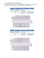
Output
Current
The
peak
output
current
is
150
mA
per
channel
in
the
grounded
load
configuration
or
75
mA
per
channel
in
the
floating
load
configuration.
The
maximum
RMS
current
is
106
mA
in
the
grounded
configuration
and
53
mA
in
the
floating
load
configuration.
The
maximum
simultaneous
output
current
from
all
channels
is
1.5
A.
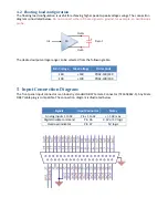
8
Power
Bandwidth
The
nominal
slew
‐
rate
of
the
PD32
in
the
grounded
load
configuration
is
19
V/us.
Therefore,
the
unloaded
maximum
frequency
sine
‐
wave
is
19
10
.
That
is,
the
power
bandwidth
for
a
120
Vp
‐
p
sine
‐
wave
is
50
kHz.
In
the
floating
load
configuration,
the
slew
‐
rate
is
doubled
to
38
V/us,
therefore,
the
power
bandwidth
for
a
240
Vp
‐
p
sine
‐
wave
is
50
kHz
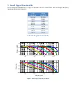
With
a
capacitive
load,
the
power
bandwidth
is
limited
by
the
output
current.
The
maximum
frequency
sine
wave
is
where
is
the
peak
current
limit,
is
the
peak
‐
to
‐
peak
output
voltage,
and
is
the
effective
load
capacitance.
The
power
bandwidth
versus
load
capacitance
is
listed
below.
Load
Peak
to
Peak
Voltage
(Grounded)
Cap.
50
100
140
10
nF
95
kHz
47
kHz
34
kHz
30
nF
31
kHz
15
kHz
11
kHz
100
nF
9.5
kHz
4.7
kHz
3.4
kHz
300
nF
3.1
kHz
1.5
kHz
1.1
kHz
1
uF
950
Hz
470
Hz
340
Hz
3
uF
310
Hz
150
Hz
114
Hz
10
uF
96
Hz
48
Hz
34
Hz
30
uF
32
Hz
16
Hz
11
Hz
Load
Peak
to
Peak
Voltage
(Floating)
Cap.
100
200
280
10
nF
23
kHz
11
kHz
8.5
kHz
30
nF
7.9
kHz
3.9
kHz
2.8
kHz
100
nF
2.3
kHz
1.1
kHz
850
Hz
300
nF
790
Hz
390
Hz
284
Hz
1
uF
230
Hz
119
Hz
85
Hz
3
uF
80
Hz
40
Hz
28
Hz
10
uF
24
Hz
12
Hz
9
Hz
30
uF
8
Hz
4
Hz
3
Hz
Table
1.
Power
Bandwidth
versus
Load
Capacitance
(Grounded
and
Floating
Load
Configuration)
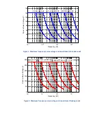
In
the
following
figures,
the
maximum
frequency
periodic
signal
is
plotted
against
the
peak
‐
to
‐
peak
voltage.


