PDN Probes
22
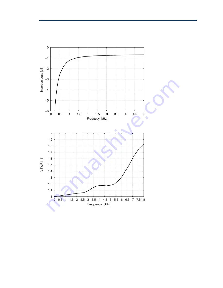
DC Block 8GHz Near DC Insertion Loss.
DC Block 8GHz VSWRs.
Page 1: ...PDN Probes Documentation Version 1 31 February 2021 Copyright 2014 2021 Picotest All Rights Reserved ...
Page 2: ...otice Except as permitted under the United States Copyright Act of 1976 no part of this publication may be reproduced or distributed in any form or by any means or stored in a data base or retrieval system without the prior written permission of Picotest Corp Information in this publication supersedes that in all previously published material Specifications are subject to change without notice Con...
Page 3: ... Error Bookmark not defined DC Blockers When and Why to Use Them 12 NISM Stability Measurement VRTS3 Board 12 2 Port Probe Applications 15 Regulator Load Step Testing VRTS3 Board 15 Low Impedance PDN Power Integrity Testing VRTS3 Board 16 Chapter 3 Accessories and Specifications 18 Specifications 18 Safety Information 19 Handling Information 20 Cleaning 20 Electrical Specifications 21 DC Blockers ...
Page 4: ...nent and connector sizes It eliminates the need for soldering SMA or coax cables to your board and the risk of damaging fine copper pads or pulling up small components You can get connectivity to circuit boards and devices without connectors The probes can be used for browser style measurement For instance if you have multiple power rails across your board the small form factor and easy probe tip ...
Page 5: ...n line probes are special types of passive probes that replace the high impedance probe cable found in a traditional passive probe with a precision transmission line that has a characteristic impedance that matches the oscilloscope s input 50Ω This greatly reduces the input capacitance to a fraction of a picofarad minimizing the loading of high frequency signals The probes are referred to as PDN p...
Page 6: ...ration dependent Using the EXTENDED 2 port setup What s Included Your Picotest Probe kit P2102A includes the following 2 Port Probe with PDN Cables P2100A CAL probe calibrator board Probe Case Documentation and Support This documentation details the use of various probes Specifications for the individual probes are also included The support section of Picotest s web site https www picotest com sup...
Page 7: ...ally useful for VRM stability measurements Usage notes Variable pin compression means variable inductance and coupling It is recommended that the same pressure pin depression be used for calibration and actual testing There may be an uncertainty of 100 200 pH The resistors on the calibrator board are all 49 9 Ohms Very small 1005 resistors are used to stay out of the way of the pins and to present...
Page 8: ...nnecting the Probe to the Instrument and Making a Measurement Connect the SMA connector of the probe to the SMA connector on the instrument If the instrument has a BNC connector then a SMA to BNC adapter is required For measurements on most instruments configure the settings as follows Input impedance of the channel 50 Ω Unit V Attenuation 1 1 You can now place the signal and ground pins on the ta...
Page 9: ... seat the four pins firmly in place The probe head should match or be larger than the capacitor you are measuring across Two pins go on each side of the capacitor Figure 2 Two signal lines go on the positive side of the capacitor and two ground lines go on the ground side of the capacitor ...
Page 10: ...PDN Probes 10 Figure 3 A 2 port measurement using a probe holder which can help supply even pressure for the four pins ...
Page 11: ...CAL probe calibrator board See your instrument s user guide for calibration instructions The calibration process can be measurement setup dependent Figure 5 Performing an SOL calibration Short left Open center and load 50 ohm right calibration ...
Page 12: ...encies between 500 Hz and 8 GHz while simultaneously providing low insertion loss and excellent VSWR Its maximum differential input output voltage is 50V Blocks can still damage RF equipment if voltages are exceeded at the instrument The blocking cap is VERY large to get to low frequency 4uF so it can transfer a lot of energy That is one reason for the attenuating probes rather than the blocks NIS...
Page 13: ... cursor measurement as shown below Figure 7 The P2102A 2 port probe in the 2 port shunt through test setup is used to measure the output impedance at the output capacitor of a power supply This same test can be performed on any power supply control loop including POLs switchers and linear regulators The software converts the output impedance to phase margin ...
Page 14: ...lity of the Infineon PS5401 at C42 is measured using NISM Top graph is the on and off state impedance The bottom graph is the QTg waveform The measurement reveals the phase margin of the voltage reference to better than 71 degrees ...
Page 15: ...ew the transient response In this example of a linear regulator load step test the J2150A Harmonic comb is used as a simple and portable square wave generator one of its modes of operation It drives the Picotest J2111A current injector This modulates the load current at the output of the regulator when the probe is applied The P2130A DC blocker may be needed so that the scope does not load the out...
Page 16: ...ere is an instrument ground loop which would otherwise distort the low frequency data Therefore it is generally required for VNA 2 port measurements Figure 10 The 2 port probe setup for a 2 port impedance stability measurement of an LDO In this case NISM software is also used to convert the impedance measurement to phase margin stability The J2102B common mode transformer is used to break the inst...
Page 17: ... Probes 17 Figure 11 The impedance data is shown to the left The group delay is shown on the right and is converted to phase margin stability via a simple cursor measurement and the built in NISM software ...
Page 18: ...ngth BNC available as an option Interchangeable Probe Tip Size Four 4 Included 0402 0603 0805 and 1206 Insulation Resistance 20Mohms Port to Port Isolation TBD Rise Time 350 ps Operating Temperature 0 to 45 C 32 F to 104 F at 80 Relative Humidity Nominal Length with Cable 1 meter Attenuation 1X 2X 5X or 10X Selected when purchased NOT Changeable Probe Pitch Fixed Calibrator Board Resistor Rating 3...
Page 19: ...ts Short circuits may cause injuries or burns Risk of injury caused by pointed object The pins of the probe are extremely pointed and can easily penetrate clothes and skin Therefore handle the probe pins with great care When transporting the probe e g when carrying it in a pocket or tool bag always use the supplied case To exchange a probe pin use tweezers or pliers to avoid injuries Use only grou...
Page 20: ...pulling Avoid mechanical shock to this product in general to guarantee accurate performance and protection Caution To avoid equipment damage and or severe injuries or death ensure that the absolute maximum ratings defined in this manual are observed at all times and never exceeded Cleaning To clean the exterior of the probe use a soft cloth moistened with either distillated water or isopropyl alco...
Page 21: ...general information to the user To achieve these results the instrument should have warmed up for at least 20 minutes and the environmental conditions should not exceed the probe s specified limits DC Blockers Electrical Specifications Figure 12 DC Blocker characteristics DC Block 8GHz Group Delay DC Block 8GHz Insertion Loss ...
Page 22: ...PDN Probes 22 DC Block 8GHz Near DC Insertion Loss DC Block 8GHz VSWRs ...
Page 23: ...PDN Probes 23 Figure 13 The effect of DC bias on the P2130A DC blocker frequency performance which shifts the 3dB frequency ...