background image

ADC-20/ADC-24 User's Guide 

About the unit 

4.1 

Introduction 

The ADC-20 and ADC-24 High-Resolution 

Data Loggers 

offer the ultimate in precise 

and accurate readings. Features such as true differential inputs, 

galvanic isolation 

and 

software-selectable sample rates all contribute to a superior 

noise-free resolution

The ADC-20 is equipped with a 20-bit A/D converter, and can maintain a gain error of 
0.2%. The four true differential inputs may be configured as eight single-ended inputs 
or any combination in between, such as two differential and four single-ended. The 
ADC-24 is equipped with a 24-bit A/D converter, and can maintain a gain error of 
0.1%. 

The eight true differential inputs may be configured as 16 single-ended inputs or any 
combination in between. Power and connection to a PC or laptop is through 

USB 

1.1, 

USB 2.0 or 3.0 port. Using the supplied PicoLog software, you can record, monitor and 
analyze collected data, even exporting to third-party applications such as Microsoft 
Excel. 

4.2 

Specifications 

Common-mode range 

Channel to common 
Channel to common 
Common to earth ground 

Input channels 

Differential 
Single-ended 

Conversion time per channel 

Input voltage ranges 

Resolution 
Noise-free resolution 
Overvoltage protection 

±1.9 V (±39 mV to ±1250 mV ranges) 

±3.0 V (±2500 mV range) 

±30 V 

ADC-20 

ADC-24 

Configurable up to 4 

Configurable up to 8 

Configurable up to 8 

Configurable up to 16 

60 ms, 100 ms, 180 ms, 340 ms, 660 ms 

2 ranges 

±1250 mV and ±2500 mV 

7 ranges 

±39 mV to ±2500 mV 

20 bits 

24 bits 

See 

table 

below 

±30 V between any input and common 

Common-mode rejection 
ratio 

Channel to common 
Common to earth ground 

Noise rejection 
Input impedance 

Gain error from source 

mpedance 

Gain error 

95 dB (DC to 60 Hz) 

>125 dB (DC to 60 Hz) 

120 dB typical at 50 to 60 Hz 

2 MΩ (differential), 1 MΩ (single-ended) 

0.5 ppm per ohm source impedance 

due to input impedance 

0.2% 

0.1% 

(0.2% at ±2500 mV) 

Offset error 

36 µV (±1250 mV range) 

400 µV (±2500 mV range) 

6 µV (±39 mV range) 
7 µV (±78 mV range) 

9 µV (±156 mV range) 

13 µV (±313 mV range) 
20 µV (±625 mV range) 

Copyright © 2005–2016 Pico Technology Ltd. All rights reserved. 

adc20.en r6 

Summary of Contents for ADC-20

Page 1: ...ADC 20 ADC 24 High Resolution Data Loggers User s Guide adc20 en r6 Copyright 2005 2016 Pico Technology Ltd All rights reserved ...

Page 2: ...ion time 11 5 ADC 20 ADC 24 terminal board 11 6 LED 11 5 Programmer s reference 12 1 Recording methods 12 2 Windows driver 12 3 Scaling 12 4 Driver functions 13 1 HRDLCloseUnit 14 2 HRDLCollectSingleValueAsync 15 3 HRDLGetMinMaxAdcCounts 16 4 HRDLGetNumberOfEnabledChannels 17 5 HRDLGetSingleValue 18 6 HRDLGetSingleValueAsync 19 7 HRDLGetTimesAndValues 21 8 HRDLGetUnitInfo 22 9 HRDLGetValues 24 10 ...

Page 3: ...ains 34 19 HRDLStop 35 5 Programming examples 36 6 Sequence of calls and data flow 37 1 Streaming recording methods 37 2 Single value recording methods 39 6 Glossary 40 7 Appendix A Connecting the data logger in Windows XP 42 Index 44 Copyright 2005 2016 Pico Technology Ltd All rights reserved adc20 en r6 ...
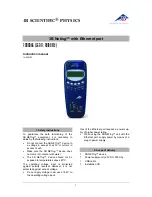
Page 4: ...should have the following items in your ADC 20 or ADC 24 package ADC 20 or ADC 24 High Resolution Data Logger Pico Technology Software and Reference CD Installation Guide The CD includes driver software that enables you to write your own programs to control the data logger using a variety of popular programming languages The hardware and software are compatible with Microsoft Windows XP SP3 or lat...

Page 5: ...to the product and or computer and could cause injury to yourself or others You should assume that the product does not have a protective safety earth Incorrect configuration and or use on voltages outside the maximum input range can be hazardous Repairs The unit contains no user serviceable parts repair or calibration of the unit requires specialized test equipment and must be performed by Pico T...

Page 6: ...nt has been tested and found to comply with the limits for a Class A digital device pursuant to Part 15 of the FCC Rules These limits are designed to provide reasonable protection against harmful interference when the equipment is operated in a commercial environment This equipment generates uses and can radiate radio frequency energy and if not installed and used in accordance with the instructio...

Page 7: ...ftware please contact our technical support staff who will try to fix the problem within a reasonable time If you are still dissatisfied please return the product and software to your supplier within 14 days of purchase for a full refund Copyright 2005 2016 Pico Technology Ltd All rights reserved adc20 en r6 ...

Page 8: ...com this is available with 32 bit or 64 bit drivers 3 2 Connecting the data logger You must install the software before plugging in the data logger When you have installed the software connect the data logger s USB cable to a spare USB port on your computer and wait until Windows displays the message Device is ready to use 3 3 Starting PicoLog To check that the data logger is working start the Pic...

Page 9: ...ial number should appear in the USB Devices list and the USB enumeration progress indicator should gradually move towards 100 If the progress indicator does not start moving disconnect and reconnect the unit and then press Refresh 7 Click OK 8 At the ADC 20 or ADC 24 channels dialog double click on Channel 1 Copyright 2005 2016 Pico Technology Ltd All rights reserved adc20 en r6 ...

Page 10: ... The PLW Recorder view should now display the voltage on channel 1 near 0 mV if nothing connected 12 Connect a suitable voltage for example from a 1 5 V battery to the channel Pin connections are marked on the logger and also listed in the Analog connector topic adc20 en r6 Copyright 2005 2016 Pico Technology Ltd All rights reserved ...

Page 11: ...o third party applications such as Microsoft Excel 4 2 Specifications Common mode range Channel to common Channel to common Common to earth ground Input channels Differential Single ended Conversion time per channel Input voltage ranges Resolution Noise free resolution Overvoltage protection 1 9 V 39 mV to 1250 mV ranges 3 0 V 2500 mV range 30 V ADC 20 ADC 24 Configurable up to 4 Configurable up t...

Page 12: ...V 1 0 V 2 mA 5 V 1 5 V 2 mA 0 ºC to 45 ºC PC connection Quoted input accuracy Storage temperature Operating humidity Storage humidity Recommended calibration nterval USB 1 1 USB 2 0 compatible Cable length approx 4 4 m 13 8 ft 20 ºC to 30 ºC 20 ºC to 60 ºC 5 to 80 RH non condensing 5 to 95 RH non condensing 1 year Input connector DB25 female Power supply 100 mA max from USB port 13 5 cm x 18 4 cm ...

Page 13: ...5 volts 24 Digital I O 2 12 2 5 volts 25 Digital I O 3 13 Digital I O 4 Note 1 Channel numbers in brackets apply when the input is set to differential mode Note 2 Channels 9 to 16 exist only on the ADC 24 Note 3 Digital I Os 1 to 4 exist only on the ADC 24 Note 4 Pins 10 and 11 are low current outputs for powering small sensors Do not exceed the current limits given in the Specifications table Not...

Page 14: ...to all of the data logger s inputs and outputs without soldering It also has space for voltage divider resistors a temperature sensor and a quad op amp See the ADC 20 ADC 24 Terminal Board User s Guide for instructions on connecting signals to the terminal board If you are not using a terminal board you can still refer to the Terminal Board User s Guide for information on connecting various types ...

Page 15: ...versions The driver exports the function definitions in standard C format but this does not limit you to programming in C You can use the API with any programming language that supports standard C calls It can also be used with programs like Microsoft Excel The driver supports all Windows operating systems from Windows 7 onwards 5 3 Scaling To convert from ADC values to volts first obtain the mini...

Page 16: ...he reading when the HRDLCollectSingleValueAsync has been called HRDLGetTimesAndValues Returns the requested number of time stamped samples for each enabled channel HRDLGetUnitInfo Writes unit information to a character string HRDLGetValues Returns the requested number of samples for each enabled channel HRDLOpenUnit Opens data logger unit HRDLOpenUnitAsync Opens unit without blocking the calling t...

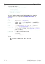
Page 17: ...t HRDLCloseUnit int16_t handle Shuts down a data logger unit Arguments handle The handle returned by HRDLOpenUnit of the unit being closed Returns 1 if a valid handle is passed 0 if not Copyright 2005 2016 Pico Technology Ltd All rights reserved adc20 en r6 ...

Page 18: ...annel Channel number to convert If the channel is not valid then the function will fail range The voltage range to be used If the range is not valid the function HRDLGetSingleValueAsync will return 0 conversionTime The time interval in which the sample should be converted If the conversion time is invalid the function HRDLGetSingleValueAsync will fail and return 0 singleEnded The type of voltage t...

Page 19: ...ents handle Handle returned by HRDLOpenUnit minAdc Pointer to an int32_t used to return the minimum ADC count available for the unit referred to by handle maxAdc Pointer to an int32_t used to return the maximum ADC count available for the unit referred to by handle channel Channel number for which maximum and minimum ADC count are required Returns 1 if a valid handle is passed 0 if not Copyright 2...

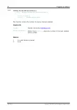
Page 20: ...ledChannels This function returns the number of analog channels enabled Arguments handle Handle returned by HRDLOpenUnit nEnabledChannels Pointer to an int16_t where the number of channels enabled will be written Returns 1 if a valid handle is passed 0 if not adc20 en r6 Copyright 2005 2016 Pico Technology Ltd All rights reserved ...

Page 21: ...nTime The time interval in which the sample should be converted See HRDLSetInterval for possible values If the conversion time is invalid the function will fail and return 0 singleEnded The type of voltage to be measured 0 differential nonzero single ended overflow Pointer to a bit field that indicates when the voltage on a channel has exceeded the upper or lower limits Bit 0 Channel 1 Bit 15 Chan...

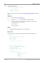
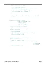
Page 22: ...the upper or lower limits Bit 0 Channel 1 Bit 15 Channel 16 Returns 1 if a valid handle is passed and the function succeeds 0 if not Sample code Code extract to get a single value reading without blocking the calling thread void main BOOL bConversionFinished FALSE int16_t channelNo int32_t value int16_t handle Open and initialize the unit Set the channel parameters channelNo HRDL_ANALOG_IN_CHANNEL...

Page 23: ...int16_t channel int16_t range int16_t singleEnded static BOOL bStartConversion FALSE int16_t overflow Test to see if the conversion has finished if bStartedConversion if HRDLReady handle HRDLGetSingleValueAsync handle lValue overflow bConversionFinished TRUE bConversionStarted FALSE Test to see if no conversion is in progress if bStartedConversion Start the conversion going bStartedConversion HRDL...

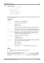
Page 24: ...ny inputs that have exceeded their maximum voltage range Channels with overvoltages are indicated by a high bit with the LSB indicating channel 1 and the MSB channel 16 noOfValues The number of samples to collect for each active channel Returns A non zero number if successful indicating the number of values returned 0 if the call failed or no values available Ordering of returned data example When...

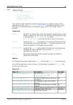
Page 25: ...en stringLength Length of the int8_t string buffer If the string is not long enough to accept all of the information only the first stringLength characters are returned info Enumerated type listed below specifying what information is required from the driver Returns The length of the string written to the int8_t string buffer string by the function If one of the parameters is out of range or a nul...

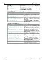
Page 26: ...gs Error Code SE_CONVERSION_TIME_OUT_OF_RANGE 0 Description The conversion time parameter is out of range SE_SAMPLEINTERVAL_OUT_OF_RANGE 1 The sample time interval is out of range SE_CONVERSION_TIME_TOO_SLOW 2 The conversion time chosen is not fast enough to convert all channels within the sample interval SE_CHANNEL_NOT_AVAILABLE 3 The channel being set is valid but not currently available SE_INVA...

Page 27: ...els with overvoltages are indicated by a high bit with the LSB indicating channel 1 and the MSB channel 16 noOfValues The number of samples to collect for each active channel Returns A non zero number if successful indicating the number of values returned or 0 if the call failed or no values available Ordering of returned data example When two analog channels e g 1 and 5 are enabled and a digital ...

Page 28: ...enUnit void This function opens a data logger The API driver can support up to 20 units Arguments None Returns 1 if the unit fails to open 0 if no unit is found 1 handle to the device opened adc20 en r6 Copyright 2005 2016 Pico Technology Ltd All rights reserved ...

Page 29: ...DLOpenUnitAsync void Opens a data logger without blocking the calling thread Arguments None Returns 0 if there is already an open operation in progress 1 if the open operation has been initiated Copyright 2005 2016 Pico Technology Ltd All rights reserved adc20 en r6 ...

Page 30: ... be written 1 if the unit fails to open 0 if no unit is found 0 a handle to the device opened this handle is not valid unless the function returns true progress Pointer to an int16_t to which the percentage progress is to be written 100 implies that the open operation is complete Returns 0 if open operation is still in progress 1 if the open operation is complete adc20 en r6 Copyright 2005 2016 Pi...

Page 31: ...y int16_t handle This function indicates when the readings are ready to be retrieved from the driver Arguments handle Handle returned by HRDLOpenUnit Returns 0 if not ready or failed 1 if ready Copyright 2005 2016 Pico Technology Ltd All rights reserved adc20 en r6 ...

Page 32: ...nts handle Handle returned by HRDLOpenUnit nValues Number of samples to collect for each active channel method Sampling method This should be one of the values listed below Returns 0 if failed 1 if successful Sampling methods Value of method Description BM BLOCK 0 Collect a single block and stop BM WINDOW 1 Collect a sequence of overlapping blocks BM STREAM 2 Collect a continuous stream of data ad...

Page 33: ... to 8 ADC 24 1 to 16 enabled Sets the channel active or dormant 0 dormant 0 active range The voltage range to be used during sampling Applies only to selected channel See Voltage ranges below singleEnded Non zero to measure a single ended voltage Zero for a differential voltage Returns 0 if failed 1 if successful If the function fails call HRDLGetUnitInfo with info HRDL_SETTINGS_ERROR 8 to obtain ...

Page 34: ...must be a combination of HRDL_DIGITAL_IO_CHANNEL constants see below digitalOutPinState If the pin is set as an output it can be set high or low by a combination of HRDL_DIGITAL_IO_CHANNEL constants see below enabledDigitalIn Sets the digital input as active Use a combination of HRDL_DIGITAL_IO_CHANNEL constants see below Returns 0 if failed 1 if successful If the function fails call HRDLGetUnitIn...

Page 35: ...12 Example bit patterns for directionOut parameter Decimal Bit Pattern Digital Channel 4 Digital Channel 3 Digital Channel 2 Digital Channel 1 0001 Input Input Input Output 10 1010 Output Input Output Input 12 1100 Output Output Input Input 13 1101 Output Output Input Output The above is a selection of the 16 different options available for the directionOut parameter When a digital channel has bee...

Page 36: ...turned by HRDLOpenUnit Time interval in milliseconds within which all conversions must take place before the next set of conversions starts The amount of time given to one channel s conversion This must be one of the constants below If the function fails call HRDLGetUnitInfo with info HRDL_SETTINGS_ERRORS for the specific settings error Conversion times Value of Conversion time conversionTime HRDL...

Page 37: ...ins noise rejection setting Rejection takes effect the next time sampling occurs Arguments handle Handle returned by HRDLOpenUnit sixtyHertz Specifies whether 50 Hz or 60 Hz noise rejection is applied 0 reject 50 Hz 0 reject 60 Hz Returns 0 if failed 1 if successful Copyright 2005 2016 Pico Technology Ltd All rights reserved adc20 en r6 ...

Page 38: ... you will need to call this function to end data collection This is particularly important in streaming mode to ensure that the scope is ready for the next capture When running the device in block mode you can call this function to interrupt data capture Arguments handle Handle returned by HRDLOpenUnit adc20 en r6 Copyright 2005 2016 Pico Technology Ltd All rights reserved ...

Page 39: ...amming examples Your Pico Technology SDK installation includes programming examples in various languages and development environments Please refer to the SDK for details Copyright 2005 2016 Pico Technology Ltd All rights reserved adc20 en r6 ...

Page 40: ...n stops Open the data logger with one of the HRDLOpenUnit calls Set mains noise rejection with HRDLSetMains Set the analog or and digital channels Set the sample interval with HRDLSetInterval Start the unit collecting samples by calling HRDLRun with method BM_BLOCK Loop Repeat Loop until ready HRDLReady Collect data with HRDLGetValues Repeat from Start the unit until you have finished collecting d...

Page 41: ...d continuously Open the data logger with one of the HRDLOpenUnit calls Set mains noise rejection with HRDLSetMains Set the analog or and digital channels Set the sample interval with HRDLSetInterval Start the unit collecting samples by calling HRDLRun with method BM_WINDOW or BM_STREAM Loop Repeat Loop until ready HRDLReady Collect data whenever you want with HRDLGetValues Call HRDLStop to end dat...

Page 42: ...nection to the unit with HRDLCloseUnit 5 6 2 2 Collecting a single reading non blocking This method collects a single reading without blocking the calling thread Open the data logger with one of the HRDLOpenUnit calls Set mains noise rejection with HRDLSetMains Start the conversion for a single reading with HRDLCollectSingleValueAsync Wait until the reading is ready HRDLReady Get the reading from ...

Page 43: ...isplay DLL Dynamic Link Library A DLL is a file containing a collection of Windows functions designed to perform a specific class of operations Driver A driver is a computer program that acts as an interface generally between a hardware component and a computer system the hardware in this case being the data logger EMC Electromagnetic compatibility The ability of a device to operate in proximity w...

Page 44: ... is the noise voltage that appears in the measurement Overvoltage protection Overvoltage protection is characterized by the maximum voltage that can be applied across the inputs of the data logger without causing damage to it The ADC 20 and ADC 24 are protected to 30 V Resolution A value in bits indicating the number of unique digital values that the converter can produce If the resolution is n bi...

Page 45: ... logger s USB cable to a spare USB port on your computer When you first plug in the device your computer should show this message and then display the New Hardware Found Wizard In the Welcome to the New Hardware Found Wizard dialog above click Next Wait while the wizard installs the software A dialog will appear like the one below Copyright 2005 2016 Pico Technology Ltd All rights reserved adc20 e...

Page 46: ...tinue to wait while the wizard installs the software When instructed click Finish to close the wizard After a few seconds you should see this message Your ADC 20 or ADC 24 Data Logger is now properly installed adc20 en r6 Copyright 2005 2016 Pico Technology Ltd All rights reserved ...

Page 47: ...etMinMaxAdcCounts 16 HRDLGetNumberOfEnabledChannels 17 HRDLGetSingleValue 18 HRDLGetSingleValueAsync 19 HRDLGetTimesAndValues 21 HRDLGetUnitInfo 22 HRDLGetValues 24 HRDLOpenUnit 25 HRDLOpenUnitAsync 26 HRDLOpenUnitProgress 27 HRDLReady 28 HRDLRun 29 HRDLSetAnalogInChannel 30 HRDLSetDigitalIOChannel 31 HRDLSetInterval 33 HRDLSetMains 34 HRDLStop 35 Humidity range 8 I Immunity 3 Input channels 8 8 I...

Page 48: ... single value blocking 39 single value non blocking 39 streaming 37 38 windowed 38 Reference output 8 Repairs 2 Resolution 8 noise free 8 S Safety warning 2 Scaling 12 Sequence of calls 37 Settings error codes 22 Single value blocking recording 39 Single value non blocking recording 39 Software installing 5 Specifications 8 Streaming 37 Streaming recording 38 Support 4 T Temperature range 8 Termin...

Page 49: ...port picotech com www picotech com adc20 en r6 2016 05 31 USA headquarters Pico Technology 320 N Glenwood Blvd Tyler Texas 75702 United States of America Tel 1 800 591 2796 Fax 1 620 272 0981 Copyright 2005 2016 Pico Technology Ltd All rights reserved Elso Philips Service Jilemnického 2 911 01 Trenèín tel 421 32 6582410 7431690 fax 421 32 6582592 email elso elso sk web www elso sk ...

Reviews: