background image

Owners Manual

7

CONTACT US 

858.546.5050

www.

picomacom

.com

PICO MACOM

Installation

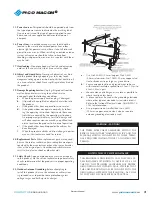
1.  Mount MPC-12C chassis onto a MOR-* steel equipment rack. Fasten the MPC-12C chassis with rack screws in the  


bottom mounting holes first then insert them into the top mounting holes.  

2.  Insert MPCMA or MPCM45 or any other compatible mini-modulator into the chassis.

3.  Mount the MPC-16PS/CS by placing it on top of the MPC-12C chassis.   


Secure the unit to the rack with four rack screws.

4.  Connect each of the 3-wire cables to the 3-pin connector at the rear of the modulator.  Caution:  When connect- 


ing the 3-wire cables align the connector with the guide tab on the 3-pin connector.  Also, be careful not to bend  


the modulator 3-pin connector.

5.  Connect the RF output of each modulator to each of the MPC-16PS/CS combiner inputs.  For best isolation 


connect each modulator in order i.e., modulator 1 to port 1, modulator 2 to port 2, modulator 3 to port 3, etc.

6.  Turn on the MPC-16PS/CS and verify that the blowers and side cooling fans are operating and the modulator power  


lights or channel displays are lit.     

®

AUDIO

VIDEO

A/V

RATIO

RF

MPCM45

®

PWR

CH

AUDIO

VIDEO

A/V

RATIO

RF

MPCM45

®

PWR

CH

AUDIO

VIDEO

A/V

RATIO

RF

MPCM45

®

PWR

CH

AUDIO

VIDEO

A/V

RATIO

RF

MPCM45

®

PWR

CH

AUDIO

VIDEO

A/V

RATIO

RF

MPCM45

®

PWR

CH

AUDIO

VIDEO

A/V

RATIO

RF

MPCM45

®

PWR

CH

AUDIO

VIDEO

A/V

RATIO

RF

MPCM45

®

PWR

CH

AUDIO

VIDEO

A/V

RATIO

RF

MPCM45

®

PWR

CH

AUDIO

VIDEO

A/V

RATIO

RF

MPCM45

®

PWR

CH

AUDIO

VIDEO

A/V

RATIO

RF

MPCM45

PWR

CH

®

AUDIO

VIDEO

A/V

RATIO

RF

MPCM45

®

PWR

CH

AUDIO

VIDEO

A/V

RATIO

RF

MPCM45

®

PWR

CH

AUDIO

VIDEO

A/V

RATIO

RF

MPCM45

®

PWR

CH

AUDIO

VIDEO

A/V

RATIO

RF

MPCM45

®

PWR

CH

AUDIO

VIDEO

A/V

RATIO

RF

MPCM45

®

PWR

CH

AUDIO

VIDEO

A/V

RATIO

RF

MPCM45

®

PWR

CH

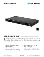
MPC-16PS/CS 

 Power Supply and Combiner/Cooling System

®

OFF

RESET

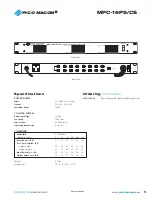
MPC-16 W/16 Modulators

MPC-16PS/CS

MPC-12C with 16 MPCM45 Modulators

MPC-16PS/CS

Summary of Contents for MPC-16PS/CS

Page 1: ...6PS CS Power Supply and Combiner Cooling System PICO MACOM Please read this manual thoroughly before use Keep this manual handy for future reference Visit Our Web Site www picomacom com Contact Us 858 546 5050 Toll Free 800 421 6511 ...

Page 2: ...s 8 Do not install near any heat sources such as radiators heat registers stoves or other apparatus including amplifiers that produce heat 9 Do not defeat the safety purpose of the polarized or grounding type plug A polarized plug has two blades with one wider than the other A grounding type plug has two blades and a third grounding prong The wide blade or the third prong are provided for your saf...

Page 3: ... product exhibits a distinct change in perfor mance this indicates a need for service 20 Replacement Parts When replacement parts are required be sure the service technician has used replacement parts specified by the manufacturer or have the same character istics as the original parts Unauthorized substitutes may result in fire electric shock or other hazards 21 Safety Check Upon completion of an...

Page 4: ...s ensuring long term reliability Pico Macom backs this product with its industry leading three year warranty MPC 16PS CS Power Supply and Combiner Cooling System High capacity blowers for superb cooling ensuring system long term reliability Reduces dust buildup in rack and on equipment Switching power supply 90 to 265Vac for installation flexibility and precise voltage regulation preventing compon...

Page 5: ...rating temperature 0 to 50 C COMBINER Bandwidth 5 860MHz Frequency MHz 5 54 216 470 600 860 Insertion Loss dB 23 23 23 23 24 26 Port Port Isolation dB Adjcent ports 40 41 42 40 37 38 Opposite ports 75 71 64 66 55 57 Input Return Loss dB 30 30 29 26 20 18 Output Return Loss dB 32 31 27 22 21 21 Weight 8 5 lbs Dimensions 19 L 9 D 1 75 H Specifications MPC 16PS CS Power Supply and Combiner Cooling Sy...

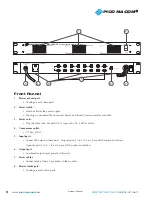
Page 6: ...t 117Vac 600W 5 Input ports Connect RF output to these ports Adjacent ports 1 to 3 to 5 etc have 38dB minimum isolation Opposite ports 1 to 2 3 to 4 etc have 55dB minimum isolation 6 Output port Combined output signal present at this port 7 Power cables Connect each of these 3 pin cables to the modules 8 Blower intake port Cooling air enters these ports OUTPUT INPUTS 1 2 3 4 5 6 7 8 9 10 11 12 13 ...

Page 7: ...nnect each modulator in order i e modulator 1 to port 1 modulator 2 to port 2 modulator 3 to port 3 etc 6 Turn on the MPC 16PS CS and verify that the blowers and side cooling fans are operating and the modulator power lights or channel displays are lit AUDIO VIDEO A V RATIO RF MPCM45 PWR CH AUDIO VIDEO A V RATIO RF MPCM45 PWR CH AUDIO VIDEO A V RATIO RF MPCM45 PWR CH AUDIO VIDEO A V RATIO RF MPCM4...

Page 8: ...lure of any product acquired by buyer from Pico Macom This limited warranty extends to the original purchaser Pico Macom reserves the right to modify or discontinue this warranty at Pico Macom s sole discretion without notification No other warrantees are expressed or implied Damage or Shortage Claims Our shipping staff carefully packs and ships your orders in compliance with common carriers requi...

Reviews: