background image

5

Rev. 11/05

Ph: 800-421-6511

www.picomacom.com

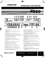
1. Video Modulation Level:

Green LED indicates correct video 

modulation level.

2. Audio Modulation Level:

Green LED indicates correct audio 

deviation level.

3.  A/V Ratio Adjustment:

Used to set level of audio carrier.

4.  Video Modulation Adjust:

Used to set the video depth of modulation

5.  Left / Right Stereo Level Adjust:

Used to set left or right channel

audio level. (Active only with stereo option)

6.  Mono Adjustment: 

Used to set mono level.

7. Channel Display: 

Indicates which channel is active.

8. Offset Indicator LEDs:

Indicate if standard or offset formats 

are active.

9. Offset Selector:

Used to select standard or offset formats.

10. 4.5MHz Level: 

Used to adjust 4.5 MHz level.

11. Output Level:

Used to set RF output level.

12. -30 dB Test Point:

Used to monitor RF output level. 

13. RF Output Port:

Connect this port to distribution system.

14. Composite I.F. Input:

Input from I.F. scrambler or I.F. output.

15. Composite I.F. Output:

To I.F. input or to scrambling device.

16. Video I.F. Input (45.75 MHz):

Video carrier I.F. input from video

scrambling device or video carrier I.F output.

17. Video I.F. Output (45.75 MHz):

Video carrier I.F. output to scrambling

device or video carrier I.F. input.

18. Audio I.F. Input (41.25 MHz):

Sound carrier I.F. input from audio

scrambling device or sound carrier I.F. output.

19. Audio I.F. Output (41.25 MHz):

Sound carrier I.F. to audio 

scrambling device or sound carrier I.F. input.

20. 4.5 MHz Input:

Input for BTSC stereo encoder operation.

21. MPX Out: 

Used to provide MPX output to additional modulators

when internal stereo encoder is present, eliminating need for 
additional encoders.

22. MPX In/Out:

Loop the MPX Input and Output when internal stereo

encoder is used.

23. Video Loop In:

Connect baseband video to this port.

24. Video Loop Out:

This port provides the video sync to external 

PM-SE stereo encoder.

25. Mono/Stereo Switch:

Selects either mono or stereo modes. Stereo

mode is only present on stereo encoder equipped models. 

26. Audio Input (Left, Right and Mono):

Accepts any baseband audio

output source such as a satellite receiver, VCR, security camera or
cable converter.

27. RS485:

Not active at the present time.

28. Power Cord Receptacle:

Connect power cord to this receptacle.

The switching power supply accepts any input voltage from 
90 to 260 VAC.

F860

Connections and Controls

F860 Manual.qxd  11/21/05  10:17 AM  Page 5

Summary of Contents for F860

Page 1: ...Installation and Operation Manual F860 Fixed Modulator Operation Manual Rev 11 05 Ph 800 421 6511 www picomacom com F860 Manual qxd 11 21 05 10 16 AM Page 1 ...

Page 2: ... pass filtering at the output amplifier The modulator is shipped with all internal adjustments preset FCC Docket 21006 offsets are standard The MACOM line is backed by an industry lead ing 5 year limited warranty Re broadcast quality performance Integrated BTSC Stereo optional 60 dBmV minimum adjustable output for optimum carrier to noise performance Preemphasis defeat switch provides easy stereo ...

Page 3: ...n Delay 8 ns Hum and Noise 60 dB AUDIO INPUT Level Mono 0 5 V p p 1 V p p Level Left Audio 0 5 V p p 1 V p p Level Right Audio 0 5 V p p 1 V p p Frequency Response 1 5 dB max Impedance 600 ohms Preemphasis 75 µs switchable MPX BTSC STEREO Level 2 2 V p p Impedance 500 ohms Frequency Response 1 dB 50 Hz 14 kHz Total Harmonic Distortion 0 3 S N 75 dB Separation 35 dB 50 Hz 12 kHz GENERAL Power Input...

Page 4: ...sons and serious damage to the appliance 8 Damage Requiring Service Disconnect this product from the system and refer servicing to qualified service personnel under the following conditions a If liquid has been spilled or objects have fallen into the product b If the product has been exposed to rain or water c If the product does not operate normally by following the operating instruction Adjust o...

Page 5: ...video carrier I F output 17 Video I F Output 45 75 MHz Video carrier I F output to scrambling device or video carrier I F input 18 Audio I F Input 41 25 MHz Sound carrier I F input from audio scrambling device or sound carrier I F output 19 Audio I F Output 41 25 MHz Sound carrier I F to audio scrambling device or sound carrier I F input 20 4 5 MHz Input Input for BTSC stereo encoder operation 21 ...

Page 6: ...evel If necessary adjust the video modulation until proper contrast is observed 6 Connect an audio source to the AUDIO IN on rear of the unit Set audio modulation peak deviation to 25 kHz with the audio modulation adjustment A known off air signal and a TV may be used to set adjustment for equal audio level 7 Connect the RF OUTPUT to a combining network FREQUENCY OFFSETS The Federal Communications...

Page 7: ...ined on one row while even channels are combined on the other row of directional couplers The combiner loss is 28 30 dB per channel Used with an L860 distribution launch amplifier the system s RF output provides high quality distortion free programming The CHC 16U 860 provides both signal combining and post amplification of the headend signals Up to 16 channels may be com bined using the CHC 16U 8...

Page 8: ...ll be used to track your product Be prepared to provide 1 The model number and channel number of the product 2 The date of purchase 3 A specific identification of the problem Deliver the products to Pico Macom Inc or ship the products in the original packing material to the address below Include satisfactory evidence of the date of purchase Products will not be accepted by Pico Macom Inc without t...

Reviews: