Page 4.6
REED RELAY MODULE 40-110/115/120/125
pickering
SECTION 4 - PROGRAMMING GUIDE
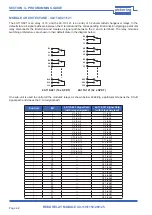
MODULE ARCHITECTURE - 40-125-121
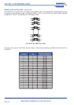
One sub-unit is used to control all the module’s relays as shown below. Enabling a particular bit closes the C to A
signal path.
Sub-Unit
Bit
40-125-121 Signal Path
(with relay energised)
1
1
C1 to A1
1
2
C2 to A2
1
3
C3 to A3
1
4
C4 to A4
1
5
C5 to A5
1
6
C6 to A6
1
7
C7 to A7
1
8
C8 to A8
1
9
C9 to A9
1
10
C10 to A10
1
11
C11 to A11
1
12
C12 to A12
1
13
C13 to A13
1
14
C14 to A14
1
15
C15 to A15
1
16
C16 to A16
1
17
C17 to A17
1
18
C18 to A18
1
19
C19 to A19
1
20
C20 to A20
1
21
C21 to A21
1
22
C22 to A22
1
23
C23 to A23
1
24
C24 to A24
The 40-125-121 is an array of 24 uncommitted screened SPST relays. In the default state, all signal paths are open.
Energising a particular relay creates a signal path between the C and A terminals. The relay module’s switching
architecture is shown in the default state in the diagram below:
40-125-121 (24 x SPST Screened)
A1
C1
S1
S1
A2
C2
S2
S2
A3
C3
S3
S3
A23
C23
S23
S23
A24
C24
S24
S24

