background image


5 Installation 

Q-632 Miniature Rotation Stage 

MP129E 

Version: 1.1.2 

21 

5.4.1


Overview: Connecting for Atmospheric Operation 


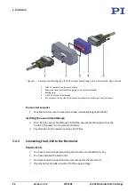
Figure 7:   Options for connecting the Q-632 to suitable electronics for atmospheric operation 

1


Controller 

2


Extension cable 

3


Mechanics 


5.4.2


Overview: Connecting for Operating in a Vacuum 


Figure 8:   Connecting the Q-632 to suitable electronics for operating in a vacuum 

1


Controller 

2


Extension cable 

3


Vacuum feedthrough for pressure to 10

-6

 hPa 

4


Mechanics 

Summary of Contents for Q-Motion Q-632

Page 1: ...www pi ws MP129E Q 632 Miniature Rotation Stage User Manual Version 1 1 2 Date 16 05 2019 This document describes the following product Q 632 930 Q Motion rotation stage piezoelectric inertia drive 3...

Page 2: ...mbH Co KG Karlsruhe Germany The text photographs and drawings in this manual are protected by copyright With regard thereto Physik Instrumente PI GmbH Co KG retains all the rights Use of said text pho...

Page 3: ...roduct Labeling 8 3 3 Scope of Delivery 9 3 4 Accessories 10 3 5 Suitable Electronics 10 3 6 Technical Features 11 3 6 1 Linear Encoder Sensor 11 3 6 2 Reference Point Switch 11 3 6 3 ID Chip 11 4 Unp...

Page 4: ...mer Service 35 10 Technical Data 37 10 1 Specifications 37 10 1 1 Data Table 37 10 1 2 Maximum Ratings 38 10 1 3 Ambient Conditions and Classifications 39 10 2 Operating Time 39 10 3 Dimensions 40 10...

Page 5: ...erstanding of basic servo systems as well as motion control concepts and applicable safety procedures The latest versions of the user manuals are available for download p 3 on our website 1 2 Symbols...

Page 6: ...of the RS 232 interface Warning sign affixed to the product that refers to detailed information in this manual 1 3 Definition of Terms Term Explanation Load capacity Maximum load capacity in the verti...

Page 7: ...loading Contact our customer service department p 35 INFORMATION For products that are supplied with software CD in the scope of delivery access to the manuals is protected by a password Protected con...

Page 8: ...1 Open the website www pi ws 2 If access to the manuals is protected by a password a Click Login b Log in with the user name and password 3 Click Search 4 Enter the product number up to the period e...

Page 9: ...tions in areas where failure would be a considerable risk for people or the environment The Q 632 is not intended for continuous operation For further information on the operating conditions of the Q...

Page 10: ...is complete Missing information due to an incomplete user manual can result in minor injury and damage to equipment Install and operate the Q 632 only after you have read and understood this user man...

Page 11: ...9 Accessories 10 Suitable Electronics 10 Technical Features 11 3 1 Product View Figure 1 Q 632 930 rotation stage 1 ESD protection cap 2 Type plate p 8 3 Connector for drive and sensor D sub 15 m 4 Wa...

Page 12: ...32 Miniature Rotation Stage Figure 2 Direction of motion of the Q 632 s platform The arrow in the figure above shows the direction of motion on positive commanding 3 2 Product Labeling Figure 3 Produc...

Page 13: ...rk A WWW PIMICOS COM Manufacturer s address website A D Manufacturer s logo A Warning sign Electrostatic sensitive devices B Symbol for the protective earth conductor marks the position of the holes v...

Page 14: ...optical table for use in a vacuum to 10 6 hPa Material Aluminum alloy anodized mass 8 g C 815 VF Vacuum feedthrough drive and sensor signals D sub 15 m f including C815T0003 technical note To order co...

Page 15: ...ition 3 6 2 Reference Point Switch The Q 632 also has an optical reference switch The commands that use the reference signal are described in the user manual for the controller and or in the correspon...

Page 16: ......

Page 17: ...to be used in a vacuum All parts are cleaned at PI before assembly Powder free gloves are worn during assembly and measuring Touch the rotation stage only with powder free gloves If necessary wipe the...

Page 18: ......

Page 19: ...e Q 632 is in contact with the surface on which the Q 632 is mounted NOTICE Unwanted changes in position when mounted vertically The motion platform could move unexpectedly if the load exceeds the rot...

Page 20: ...the Q 632 onto an Underlying Surface and Connecting it to a Protective Earth Conductor NOTICE Protruding screw heads Protruding screw heads can damage the Q 632 Ensure that the screw heads do not pro...

Page 21: ...Two of the four available locating holes can be used for alignment on a surface Figure 5 Top of the Q 632 The rotation stage is fixed to the underlying surface with four screws 4 socket head screws ou...

Page 22: ...Insert the two locating pins into the locating holes in the bottom of the Q 632 see figure above or in the underlying surface 2 Put the Q 632 onto the underlying surface so that the locating pins are...

Page 23: ...the correct length for the respective mounting holes only Figure 6 Black arrows indicate locating holes for alignment of the load whereas white arrows indicate threaded holes for fixing the load Requi...

Page 24: ...in the motion platform are aligned If you use locating pins to align the load a Insert the locating pins into the locating holes in the motion platform or in the load b Place the load on the motion pl...

Page 25: ...for connecting the Q 632 to suitable electronics for atmospheric operation 1 Controller 2 Extension cable 3 Mechanics 5 4 2 Overview Connecting for Operating in a Vacuum Figure 8 Connecting the Q 632...

Page 26: ...ectronics Tools and accessories Four M3 stainless steel countersunk screws of suitable length ISO 7046 Installing the vacuum feedthrough For C 815 VF vacuum feedthrough Install the vacuum feedthrough...

Page 27: ...epare the Q 632 for connecting Remove the ESD protection from the Q 632 s connector When a Q 632 is to be operated in a vacuum Installing the vacuum feedthrough a Obtain the dimensions from the corres...

Page 28: ......

Page 29: ...ications reconnect the Q 632 to the protective earth conductor before restarting CAUTION Burning from hot surface The surface of the Q 632 and its vicinity can heat up during operation Touching the Q...

Page 30: ...pecified for the Q 632 NOTICE Reduced lifetime of the piezo actuator due to permanently high voltage Applying a high static voltage to piezo actuators continuously reduces the lifetime of the piezo ce...

Page 31: ...y of the electronics in step mode step frequency respectively the velocity see the user manual for the electronics Reduce the operating time with a high operating frequency p 39 Stop the motion immedi...

Page 32: ...e software from the scope of delivery of the electronics the operating parameters can be loaded from PIMicosStages3 dat The records in the positioner database are updated regularly Install the PI Upda...

Page 33: ...he parameters for the operating frequency in step mode or the velocity see the user manual for the electronics to your application see also General Notes on Startup and Operation p 25 and Operating Ti...

Page 34: ......

Page 35: ...The maintenance run must comprise at least one full rotation of the motion platform of the Q 632 Do the maintenance run after every 10 million steps 7 3 Cleaning the Q 632 Requirements You have discon...

Page 36: ......

Page 37: ...erts a torque that is lower than the drive torque p 37 when the rotation stage is mounted vertically e g cables connected to the load should have sufficient strain relief Parameters of the electronics...

Page 38: ...p 39 Drive wear Replace the Q 632 and make sure that the operating parameters of the electronics are adapted to the rotation stage Drive is blocked Release the blockage carefully by turning the motio...

Page 39: ...formation Product and serial numbers of all products in the system Firmware version of the controller if applicable Version of the driver or the software if applicable Operating system on the PC if ap...

Page 40: ......

Page 41: ...position sensor for closed loop operation Active axis Z Rotation range 360 Integrated sensor Incremental encoder Sensor resolution 0 75 rad Minimum incremental motion 3 rad typ Unidirectional repeata...

Page 42: ...tor D sub 15 Recommended electronics E 873 1AT E 873 3QTU E 873 10C885 For operation in a vacuum we recommend a reduced duty cycle of 20 and a reduced rotation speed of 50 compared to a standard envir...

Page 43: ...tched off state Overvoltage category according to EN 60664 1 VDE 0110 1 II Protection class according to EN 61140 VDE 0140 1 I Degree of pollution according to EN 60664 1 VDE 0110 1 1 Degree of protec...

Page 44: ...10 Technical Data 40 Version 1 1 2 MP129E Q 632 Miniature Rotation Stage 10 3 Dimensions Dimensions in mm Note that a comma is used instead of a decimal point in the drawings Figure 10 Q 632 930...

Page 45: ...10 Technical Data Q 632 Miniature Rotation Stage MP129E Version 1 1 2 41 10 3 1 Q 101 AP1 Adapter Plate Dimensions in mm Figure 11 Q 101 AP1 adapter plate...

Page 46: ...1 1 2 MP129E Q 632 Miniature Rotation Stage 10 3 2 C 815 VF Vacuum Feedthrough for 10 6 hPa Dimensions in mm Note that a comma is used in the drawings instead of a decimal point Figure 12 C 815 VF vac...

Page 47: ...ber opening for the C 815 VF vacuum feedthrough for 10 6 hPa Dimensions in mm Note that a comma is used in the drawings instead of a decimal point Figure 13 Top View of the opening on the air side mid...

Page 48: ...nal differential Output 2 Motor Motor signal differential Input 3 Motor Motor signal differential Input 4 VDD Supply voltage 5 V Input 5 6 ID chip data ID chip data Output 7 SIN Encoder A Output 8 COS...

Page 49: ...side m Pin Signal Function Pin 1 REF Reference signal differential 1 2 Motor Motor signal differential 2 3 Motor Motor signal differential 3 4 VDD Supply voltage 5 V 4 5 5 6 ID chip data ID chip data...

Page 50: ......

Page 51: ...ccording to international national and local rules and regulations In order to fulfil the responsibility as the product manufacturer PI miCos GmbH undertakes environmentally correct disposal of all ol...

Page 52: ......

Page 53: ...claration of Conformity has been issued in accordance with the following European directives Low Voltage Directive EMC Directive RoHS Directive The applied standards certifying the conformity are list...

Reviews: