background image


5 Installation 

P­763 Nanopositioner 

PZ258E 

Version: 1.1.0 

15 

In this Chapter 

General Notes on Installation ...................................................................................................... 15 

Connecting the P-763 to the Protective Earth Conductor ........................................................... 16 

Mounting the P-763 ..................................................................................................................... 18 

Fixing the Load ............................................................................................................................. 19 


5.1


General Notes on Installation 


CAUTION 


Dangerous voltage and residual charge in piezo actuators! 

The P-763 is driven by piezo actuators. Temperature changes and compressive stress can 

induce charges in piezo actuators. Piezo actuators can remain charged for several hours after 

disconnecting from the electronics. Touching or short-circuiting the contacts in the P-763's 

connectors could lead to minor injuries from electric shock. The piezo actuators can be 

destroyed by an abrupt contraction. 


Do 

not

 open the P-763. 


Discharge the P-763's piezo actuators before installing: 

Connect the P-763 to the switched-off electronics from PI equipped with an internal 

discharge resistor. 


Do 

not

 pull the connectors out of the electronics during operation. 


Touching the contacts in the connectors can lead to an electric shock (max. 130 V DC) and 

minor injuries. 


Do 

not

 touch the contacts in the connectors. 


Use screws to secure the P-763's connectors against being pulled out of the electronics. 


NOTICE 


Mechanical overload due to incorrect handling! 

An impermissible mechanical load on the platform of the P-763 can cause damage to the piezo 

actuators, sensors, and flexures of the P-763 as well as loss of accuracy. 


Do 

not

 touch any sensitive parts (e.g., platform) when handling the P-763. 


5


Installation 

Summary of Contents for P--763 Series

Page 1: ...721 4846 0 Fax 49 721 4846 1019 Email info pi ws www pi ws PZ258E P 763 Nanopositioner User Manual Version 1 1 0 Date 17 06 2020 This document describes the following product P 763 22C Compact XY nan...

Page 2: ...I GmbH Co KG Karlsruhe Germany The text photographs and drawings in this manual are protected by copyright With regard thereto Physik Instrumente PI GmbH Co KG retains all the rights The use of any te...

Page 3: ...ct Labeling 10 3 3 Scope of Delivery 11 3 4 Suitable Electronics 11 3 5 Required Accessories 11 3 6 Technical Features 12 3 6 1 PICMA Piezo Actuators 12 3 6 2 Flexure Guides 12 3 6 3 Capacitive Sensor...

Page 4: ...mer Service 31 10 Technical Data 33 10 1 Specifications 33 10 1 1 Data Table 33 10 1 2 Maximum Ratings 34 10 2 Ambient Conditions and Classifications 34 10 3 Dimensions 35 10 4 Torque for Stainless St...

Page 5: ...chnology drive technologies and suitable safety measures is assumed The latest versions of the user manuals are available for download p 3 on our website 1 2 Symbols and Typographic Conventions The fo...

Page 6: ...lors proportions and degree of detail in illustrations can deviate from the actual circumstances Photographic illustrations may also differ and must not be seen as guaranteed properties 1 4 Other Appl...

Page 7: ...t p 31 Downloading manuals 1 Open the website www pi ws 2 Search the website for the product number e g P 763 or the product family e g Nanopositioner 3 Click the corresponding product to open the pro...

Page 8: ......

Page 9: ...h suitable electronics p 11 available from PI The electronics are not included in the P 763 s scope of delivery The electronics must provide the required operating voltages To ensure proper performanc...

Page 10: ...with an internal discharge resistor Do not pull the connectors out of the electronics during operation Do not touch the contacts in the connectors Use screws to secure the P 763 s connectors against b...

Page 11: ...al notes If you give the P 763 to a third party include this user manual as well as other relevant information provided by the manufacturer Do the work only if the user manual is complete Missing info...

Page 12: ......

Page 13: ...essories 11 Technical Features 12 3 1 Product View The figure serves as an example and can differ from your positioner model Figure 1 Exemplary product view of the P 763 1 Base body 2 Platform 3 Cable...

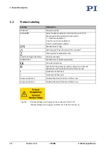
Page 14: ...o the manual Old equipment disposal p 39 Country of origin Germany Country of origin WWW PI WS Manufacturer s address website CE conformity mark Symbol for the protective earth conductor marks the pro...

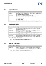
Page 15: ...itive sensors D sub 25W3 socket E 727 3CDA Digital multi channel piezo controller 3 axes 30 to 130 V capacitive sensors D sub 25W3 socket analog inputs E 727 3CDP Digital multi channel piezo controlle...

Page 16: ...sliding parts Flexure elements have a high stiffness and load capacity Flexure guides are maintenance and wear free They are 100 vacuum compatible function in a wide temperature range and do not requi...

Page 17: ...as well as loss of accuracy Do not touch any sensitive parts e g platform when handling the P 763 1 Unpack the P 763 with care 2 Compare the contents with the scope of delivery according to the contr...

Page 18: ......

Page 19: ...piezo actuators can be destroyed by an abrupt contraction Do not open the P 763 Discharge the P 763 s piezo actuators before installing Connect the P 763 to the switched off electronics from PI equipp...

Page 20: ...ectly tightened screws can cause damage Pay attention to the torque range p 36 specified for the screws used during installation INFORMATION Extension cables can reduce the positioning accuracy of the...

Page 21: ...cting the protective earth conductor Suitable screwdriver Figure 3 Connecting the protective earth conductor profile view 1 Base body of the P 763 2 Flat washer 3 Lock washer 4 Screw 5 Cable lug 6 Pro...

Page 22: ...expansion properties as the P 763 NOTICE Tensile stress when mounted vertically When the P 763 is mounted vertically certain alignments can cause tensile stress that reduces the preload and destroys...

Page 23: ...es in the base body and the underlying surface are in line 2 Mount the P 763 from below onto the underlying surface a Insert the screws through the holes in the underlying surface into the base body o...

Page 24: ...y from the center of the platform e g tall loads and unwanted lever effect the P 763 can be damaged by high strain on the flexure guides high torques and oscillation especially when operated dynamical...

Page 25: ...he electronics Tools and accessories Screws of suitable size and length p 35 Suitable screwdriver Fixing the Load 1 Align the load on the P 763 so that the mounting holes in the load and the holes in...

Page 26: ......

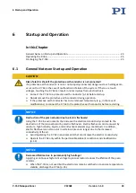
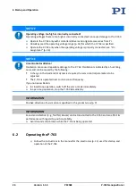
Page 27: ...ect the P 763 to the protective earth conductor before restarting NOTICE Destruction of the piezo actuator due to electric flashovers Using the P 763 in environments that increase the electrical condu...

Page 28: ...n is indicated by a humming noise and can be caused by the following A change in the load and or dynamics requires the servo control parameters to be adjusted The P 763 is operated near to its resonan...

Page 29: ...ing and transporting the P 763 and for modifications The P 763 is discharged via the discharge resistor inside the electronics from PI Discharging a positioner connected to the electronics In closed l...

Page 30: ......

Page 31: ...o actuators Loosened screws cause a loss in positioning accuracy Loosen screws only when instructed in this manual Do not open the P 763 7 2 Cleaning the P 763 NOTICE Damage from ultrasonic cleaning U...

Page 32: ......

Page 33: ...far above or below the calibration temperature 21 C to 24 C Adjust the zero point of the sensor see controller manual Reduced positioning accuracy The base body or the platform is warped Mount the P 7...

Page 34: ...nding motion axes immediately 2 Check the settings of the servo control parameters on the controller 3 Adjust the servo control parameters on the controller according to the load change Open loop oper...

Page 35: ...tion Product and serial numbers of all products in the system Firmware version of the controller if applicable Version of the driver or the software if applicable Operating system on the PC if applica...

Page 36: ......

Page 37: ...esolution in X Y open loop 1 nm Typ Resolution in X Y closed loop 2 nm Linearity error in X Y 0 02 Typ Repeatability X Y 5 nm Typ Mechanical properties Resonant frequency in X under load 260 g 180 Hz...

Page 38: ...for maximum power consumption Details can be found at the following website https www physikinstrumente com en technology piezo technology properties piezo actuators electrical operation 10 2 Ambient...

Page 39: ...10 Technical Data P 763 Nanopositioner PZ258E Version 1 1 0 35 10 3 Dimensions Dimensions in mm Figure 8 P 763 22C...

Page 40: ...Nm M5 2 5 Nm 3 5 Nm M4 1 5 Nm 2 5 Nm M3 0 8 Nm 1 1 Nm M2 5 0 3 Nm 0 4 Nm M2 0 15 Nm 0 2 Nm M1 6 0 06 Nm 0 12 Nm Pay attention to the screw in depth required for the respective material according to th...

Page 41: ...voltage A2 Probe Probe sensor signal immovable part of the capacitive sensor 1 Data ID chip Data line for ID chip 2 GND Target and ID chip Target and ID chip ground 3 GND PZT Piezo voltage ground 4 n...

Page 42: ......

Page 43: ...ational national and local rules and regulations In order to fulfil its responsibility as the product manufacturer Physik Instrumente PI GmbH Co KG undertakes environmentally correct disposal of all o...

Page 44: ......

Page 45: ...Conformity has been issued in accordance with the following European directives Low Voltage Directive EMC Directive RoHS Directive The applied standards certifying the conformity are listed below Safe...

Reviews:

Related manuals for P--763 Series