3
www.phywe.com, © All rights reserved
12973-00 / 1821
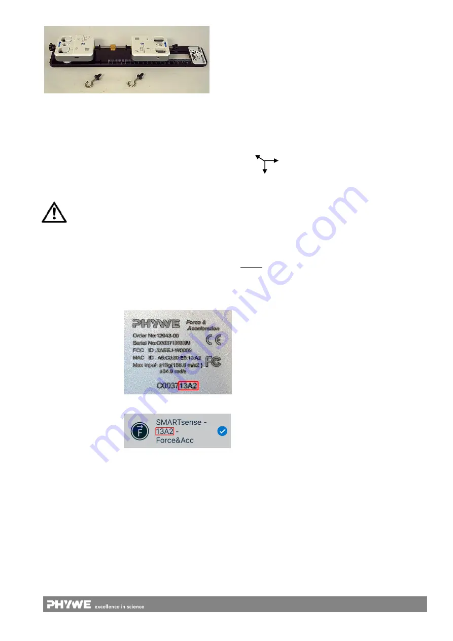
Fig. 6 Structure with rigid screw connection
5.1 Charging the Force & Acceleration Sensor
Use a USB-C cable to connect the sensor to a computer or
USB charger (not included).
During the charging process, the battery charge LED lights
up red. When the charging process is complete, the battery
charge LED lights up green. The charging time for a com-
pletely discharged battery is 3 hours maximum.
Disconnect the charger at the latest four hours af-
ter the completion of the charging process. Other-
wise, the service life of the battery may be nega-
tively affected.
5.2 Start-up
Switch on the sensor by pressing the power button for more
than 3s. Now the Bluetooth LED flashes red. Start the soft-
ware and select the sensor.
If the sensor is to be used via the USB interface, it does not
need to be switched on. The sensor is connected directly to
the end device using the supplied USB cable.
There is a 9-digit code
on the back of the sen-
sor (Fig.2). The last 4
digits of the code are
displayed as the sensor
name in the software
(Fig.3). This enables
the precise assignment
of the sensors within
the software.
Fig. 2
Fig. 3
Selection of the sensor via the Bluetooth interface
Make sure that the Bluetooth interface is activated on the
terminal device (PC/Tablet/Smartphone) and that the soft-
ware is allowed to access the interface.
After the sensor has been selected in the software, the LED
flashes green to indicate that the connection has been estab-
lished correctly. After the sensor has been coupled with the
software, the sensor is no longer visible to other users in the
software, and therefore can no longer be selected.
If the sensor is switched on and not connected, it switches off
automatically after 5 minutes.
Selection of the sensor via the USB interface
For this purpose the sensor must be plugged into the USB
port of the end device. It is not necessary to switch on the
sensor. The sensor is automatically recognized and dis-
played. It can be selected and connected directly.
Force sensor:
The force signal is determined by means of strain gauges on
a bending beam. The force is applied along the main axis of
the sensor.
Acceleration:
Acceleration values are measured on 3 axes.
The symbol on the front of the sensor shows the assignment
of the axes in positive directions.
Gyroscope:
The gyroscope measures the rate of rotation of the sensor.
The printed 3-axis symbol represents the axes of rotation.
6 TECHNICAL DATA
Operating temperature range: 5 - 40°C
Rel. humidity < 80%
Sensor
Force:
Measuring range
Resolution
Acceleration:
Measuring range
Resolution
Gyroscope:
Measuring range
Resolution
Accuracy*
±50 N
30mN
± 16 g
0,01 g
34,9 rad/s
0,01 rad/s
± 1 %
Max. date rate
Battery capacity
Max. wireless range (open field)
1000 Hz
250 mAh
30 m
Dimensions (length x width x height)
320x80x60 mm
Weight
0,45 kg
*referred to the full-scale value
7 SCOPE OF DELIVERY
The scope of delivery includes:
2x Cobra SMARTsense Force & Acceleration 12943-00
2x USB connection cable type C07935-00
Set threaded connection
3x magnetic connector
1x base plate
1x sledge
Z
X
Y


