phytron
MA 1203-A010 EN
17
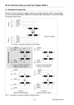
8-leads stepper motors
have two leads from each of the four motor windings (see Fig. 6,
upper drawing). These motors can be driven by all types of control units in bipolar and uni-
polar operating modes.
4-leads stepper motors
(windings parallel or serially connected, see Fig. 6, middle) are
designed for bipolar operation mode.
Bipolar operation mode
– parallel or series winding connection
Low control pulse frequency: When operated with maximum allowable phase current
(see table below), with both connection modes the same motor torque is generated.
With rising frequency, the torque drops off sooner with serial windings.
Reason: The motor's inductance is four times higher (compared to unipolar operation
or bipolar operation with parallel windings).
Operation with low control pulse frequencies
The motor has up to 40 % more torque in the bipolar mode (compared to unipolar control)
with the same phase current, at low frequencies.
5-lead or 6-lead stepper motors
(Fig. 6, below) can be driven by unipolar control units.
The
cable cross section
for the connection leads should be selected according to the
cable length. Please follow the advice in the stepper motor power stage manual.
6.1 Maximum Allowable Phase Current
The motor rating plate has the rated phase current [A] as the last digits of the motor's type
number.
Example: VSS 32.200.
1,2
Motor type VSS 32, 200 steps/rev., 1.2 A rated current
The
rated current
is the maximum allowable current at full step operation, at bipolar con-
trol mode, with parallel-connected windings (standard).
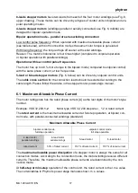
Maximum Allowable Phase Current
bipolar control mode
full step operation
unipolar control mode
full step operation
4-lead motor
parallel windings
4-lead motor
serial windings
5-lead motor
6-lead motor
rated current
50% of rated current
70.7% of rated current
70.7% of rated current
The
maximum allowable power dissipation
of a stepper motor is always the same for all
connection modes. According to the connection mode, the motor windings receive different
currents. Therefore, the maximum allowable phase currents are determined by the con-
nection mode.
At
half-step or mini-step
operation of the control unit, the rated current is the r.m.s value.
The current tables in Phytron's power stage manuals show r.m.s. values.


