L-843e.A1 phyBOARD-Mira i.MX 6 Hardware Manual
© PHYTEC Messtecknik GmbH
30
FIGURE 10: PCIe Interface at Connector X7
card signals of a connected PCIe module can be made available at expansion connector X17. Please
refer to
for more information about the jumper settings. Soldering jumpers connect the USB
host interface to the Mini PCIe connector X7 (
). The following table is a complete overview of the
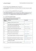
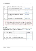
Mini PCI Express connector pin assignment.
TABLE 16: Mini PCI Express Connector X7
Pin
#
Signal Name
Signal
Type
Signal
Level
Description
1
X_ECSPI2_MOSI/
PCIe_nWAKE
IN
3.3 V
PCIe WAKE
2
VCC3V3
OUT
3.3 V
3.3 V power supply
3
X_ECSPI2_SS0/PCIe_COEX1
I/O
3.3 V
Coexistence pins for wireless solutions
4
GND
-
-
Ground
5
X_CSI1_DATA06/
PCIe_COEX2
I/O
3.3 V
Coexistence pins for wireless solutions
6
VCC1V5
OUT
1.5 V
1.5 V power supply
7
X_ECSPI2_SCLK/
PCIe_nCLKREQ
IN
3.3 V
Clock request support
8
X_SIM_VCC
IN
-
9
GND
-
-
Ground
10
X_SIM_IO
I/O
-
11
X_PCIe0_CLK-
OUT
DIFF
PCIe0 reference clock -


