FASTCAM MC1 Hardware Manual
31
2.4.2. Startup Screen
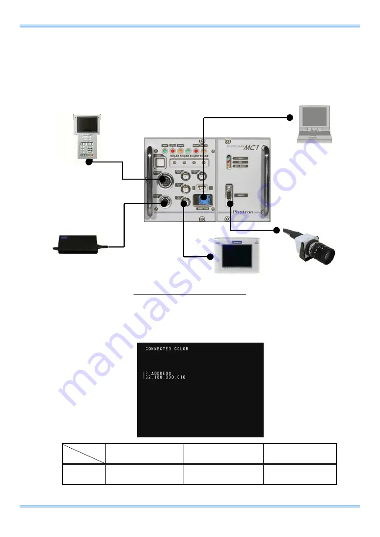
1. After attaching the imager, cables, keypad, and external devices as explained in the
previous section, turn the power on by pressing the
power switch
on the front of the camera
controller.
Example Cable/Device Connections
2. After switching on the power, the
imager connection status
and
current IP address
setting
is displayed as text on the video monitor screen.
Monochrome
Imager
Connection
Color Imager Connection
No Connection
Screen
Display
CONNECTED MONO
CONNECTED COLOR
NOT CONNECTED
Connect to Gigabit Ether
Connect to Imager
Connect to Video Out
Connect to Keypad
Connect to DC18-36V
Video monitor
PC
Imager
Keypad
AC adapter
Summary of Contents for Fastcam MC1
Page 1: ...FASTCAM MC1 Hardware Manual Revision 1 02E ...
Page 13: ...11 Chapter 1 Overview 1 1 Product Overview and Features ...
Page 19: ...FASTCAM MC1 Hardware Manual 17 2 2 2 Camera Controller Part Names Front Panel ...
Page 96: ...Chapter 3 Recording 94 MEMO ...
Page 113: ...111 Chapter 6 System Settings 6 1 Display Settings 6 2 Other Detailed Settings ...
Page 124: ...Chapter 6 System Settings 122 MEMO ...
Page 125: ...123 Chapter 7 Product Specifications 7 1 Specifications 7 2 Dimensions ...
Page 137: ...135 Chapter 8 Warranty 8 1 About the Warranty ...
Page 139: ...137 Chapter 9 Contacting Photron 9 1 Contacting Photron ...


