


EDF ENR PWT
D06
‐
P06
‐
01
Indice
1
Date:
3
‐
01
‐
13
EDF
ENR
PWT
Société
par
actions
simplifiée
à
associé
unique
–
au
capital
de
37
505
000
€
‐
N°
513
281
972
RCS
NANTERRE
Siège
social
:
100
Esplanade
du
Général
de
Gaulle
–
Cœur
Défense
–
Tour
B
92932
Paris
La
Défense
cedex
.
33,
Rue
Saint
Honoré
‐
Z.I.
Champfleuri
38300
Bourgoin
Jallieu
‐
France
Tel
:
04
74
93
80
20
‐
Fax
:
04
74
93
80
40
To connect in parallel, use specific terminals and equipment: connect cables from the positive connector of
the module to the positive connector of the terminal.
Quantity of bypass diodes provided can vary depending on model series.
Connect the quantity of modules that match the voltage specifications of the inverters used in the system.
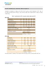
Modules must not be connected together to create a voltage higher than the permitted maximum system
voltage, even under the worst local temperature conditions (see table 1 for correction coefficients to apply
for open-circuit voltage).
A maximum of two strings can be connected in parallel without using over-current protection device
(fuses…) incorporated in series within each string. Three or more strings can be connected in parallel if an
appropriate and certified over-current protection device is installed in series with each string.
Similar electrical performance modules should be connected in same series to avoid or minimize mismatch
effects in arrays.
To minimize risk in the event of an indirect lightning strike, avoid forming loops when designing the
system.
The recommended maximum series fuse rating is tabulated in annex.
Modules should be firmly fixed in place in a manner suitable to withstand all expected loads, including
wind and snow loads. A minimum clearance of 6.5 mm (1/4 of an inch) or more between modules is
required to allow for thermal expansion of the frames.
Small openings for water draining on the underside of the module should not be blocked after mounting.
Optimum orientation and tilt
Find out the optimum orientation and tilt of the PV modules for your region to achieve the maximum annual
yield. Generation of maximum power occurs when sunlight shines perpendicularly onto the PV modules.
Avoid shading
Even the slightest partial shading (e.g. from dirt deposits) will cause a reduction in yield. A module is
considered "shadow-free" if it is unobstructed across its entire surface for the whole year. Even on the
shortest day of the year, unobstructed sunlight can reach the module.
Reliable ventilation
Sufficient clearance (at least 10 cm) between the module frame and the mounting surface is required to
allow for cooling air to circulate around the back of the module. This also allows for condensation or
moisture to dissipate.
Grounding
Although the modules are certified to safety class II, it is recommended that they be grounded and the
module installation complies with all local electrical codes and regulations.
The earth grounding conne
ction should
be made by a qualified electrician.
Connect module frames to each other using adequate grounding cables (recommended size 4-14mm
2
,
copper wires). Holes provided for this purpose are identified with a green label. All the junctions on the
conductive connection must be fixed.
The bolts, nuts, flat washers, lock washers or other relevant hardware should be made with stainless steel.
Grounding hardware is not provided by EDF ENR PWT.
5


