Phonic Ear PE 210 User Instructions Download Page 4

1

E

ASY

L

ISTENER

by Phonic Ear

GETTING STARTED

I

NSTALLING THE

AT578–S S

PEAKERS

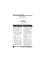
The location and position you select for
your AT578-S Speakers will play an
important role in the room’s overall sound
quality. Everything from furniture to room
configuration can effect sound dispersion.
Therefore, it is a good idea to experiment
with a number of possible locations before
you decide on the final arrangement.

Ideally, speakers should be mounted on
walls near the ceiling; however, the speakers
may also be placed on a flat surface (such as
a bookcase) or mounted to speaker stands.
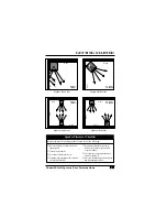
Consider the following suggestions when
determining speaker location:

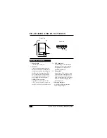
• Avoid placing speakers flush with corner

walls or ceiling (see Figures 1 and 2).

• The speakers should be placed against 

the wall, approximately 8 to 12 ft 
(2.5m to 3.5m) above the floor.

• The speakers should be angled to point

toward the listeners’ ear level.

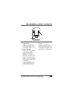
• Place speakers so that the sound trans-

mission is equal for all individuals in 
the listening area.

• Position speakers so that furniture does

not block sound dispersion.

• Avoid placing speakers directly opposite

each other or opposite a large reflective
surface; stagger them instead (see Figures
3 and 4).

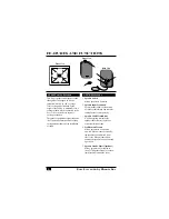
When you’ve established suitable locations
for your speakers:

• Connect a speaker cable to each speaker,

matching black to black and red to red for
correct polarity.

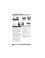
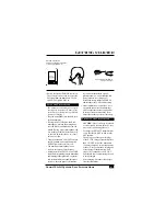
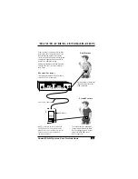
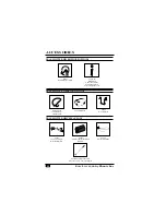
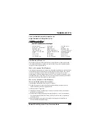
AT534 Wall Transformer/

Two-Unit Charger

PE 300T Transmitter 
with AT655 BTN Microphone 
or other appropriate mic
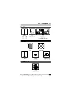
W

HAT

Y

OU

N

EED

To start using your new sound field system, make sure you have these items:

PE 210R or PE 210FSR Receiver

with AT577 Wall Transformer and Antenna

AT578-S Speakers with 

AT581 Speaker Cable 

(1 per speaker)

AT664 

Ceiling Speaker

with AT581 Cable

O

R

Summary of Contents for PE 210

Page 1: ...PE 210 Sound Field System User Instructions...

Page 2: ...fatigue lower special education costs Your new sound field system is very easy to use however we recommend that you read the entire User Instructions booklet to become familiar with all the features a...

Page 3: ...g The PE 210R Receiver 3 Using Charging The PE 300T Transmitter 4 Features and Functions PE 210R 210FSR Receiver 5 PE 300T Transmitter 7 AT664 Ceiling Speaker AT578 S Speakers 9 Team Teaching Configur...

Page 4: ...e wall approximately 8 to 12 ft 2 5m to 3 5m above the floor The speakers should be angled to point toward the listeners ear level Place speakers so that the sound trans mission is equal for all indiv...

Page 5: ...o the walls Is speaker angle pointing at the listeners ear level when seated Is equipment located in areas away from excessive heat or cold wetness or open windows Are you using the proper hardware to...

Page 6: ...tlet that is central to the location of the speakers and verify that the power switch is in the off position Plug in the AT577 Wall Transformer NOTE Install your sound field receiver at least 5 feet a...

Page 7: ...se treble in a sound absorptive room i e one with carpet soft furniture etc and decrease treble in a sound reflective room i e one with hard walls floors furniture etc See page 5 If feedback occurs re...

Page 8: ...quipment plugged into the AUX INPUT jack on the back of the receiver 6 Tone Control Allows the system to be adjusted for best performance in various listening environments Turn the knob clockwise to i...

Page 9: ...on of the transmitted FM signal 11 Channel Number PE 210R only Identifies the operating channel of the PE 210R Receiver Transmitter and receiver channel numbers must match for the units to operate tog...

Page 10: ...cord during use NOTE When an external microphone is not being used the AT529 Antenna must be plugged into the MIC jack for proper transmission 3a AUX Input Jack For connecting an external sound source...

Page 11: ...o not recharge disposable or rechargeable Alkaline batteries they may rupture and damage the unit When replacing batteries carefully note the markings inside the battery compartment for proper placeme...

Page 12: ...ost even distribution of sound AT578 S SPEAKERS 1 Speaker Switch Allows speakers to be muted 2 Speaker Input Terminals Push terminals allow for connection of speaker cable Black and red color coding e...

Page 13: ...via the AT653 input cord Team teaching is a great way to maximize learning Because two teachers can divide their time among students team taught classes can offer children more learning and participa...

Page 14: ...Neck Mic TRANSMITTER WEARING OPTIONS TRANSMITTER MISCELLANEOUS AT534 Two Unit Charger Wall Transformer AT544 2AA Rechargeable NiCad Batteries AT529 Mic Jack Antenna AT532 Auxiliary Input Cord 5 ft or...

Page 15: ...565 72 MHz AT566 173 MHz AT580 System Carrying Case AT653 AUX Input Cord 30 in 76 cm For use with dual presenters or with secondary audio sources AT577 Wall Transformer AT578 S Speaker AT579 Speaker S...

Page 16: ...oo close to the speakers Verify that only the AT291 Directional Mic or AT655 Behind the Neck Mic is being used with the 300T Transmitter Weak Output from Speaker s Increase FM and or AUX VOL control C...

Page 17: ...72 825 Green Brown 17 72 875 Black Gray 18 72 925 Green Red 19 72 975 Black Brown 20 74 625 White Brown 33 74 675 White Red 34 74 725 White Orange 35 74 775 White Yellow 36 MEDIUM 75 225 White Green 3...

Page 18: ...Commission in the U S and Industry Canada Other government approvals available upon request Other international regulations may also apply NOTE FCC Rules Part 15 Subpart A 15 19 a 3 and c This device...

Page 19: ...ly under normal use during the life of this warranty will be replaced or repaired at no charge for parts or labor when returned to the factory service center Transportation of defective components to...

Page 20: ...Ear Ltd 3880 Cypress Drive 9140 K Guilford Road 10 7475 Kimbel Street Petaluma CA 94954 7600 Columbia MD 21046 1890 Mississauga Ontario U S A U S A L5S 1E7 Canada 800 227 0735 800 638 2680 800 263 87...

Reviews: