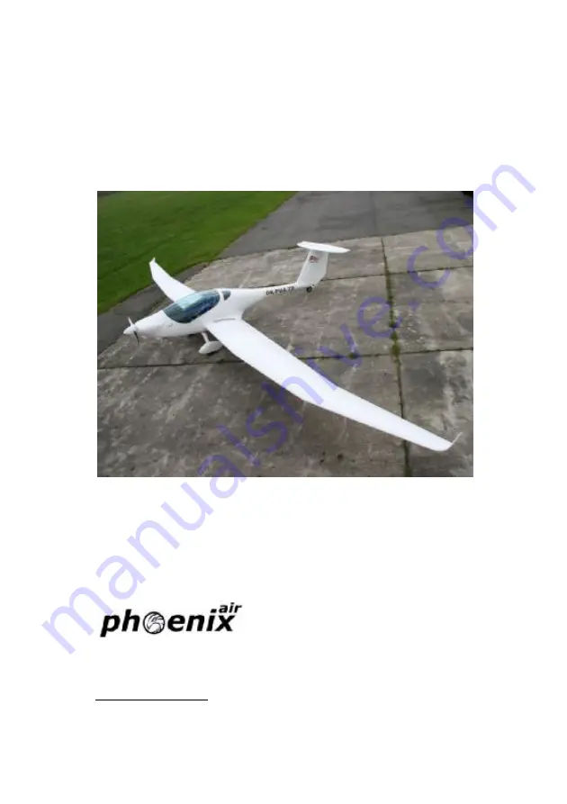
FLIGHT MANUAL FOR ULTRALIGHT
AEROPLANE
U–15 Phoenix
Registration:
LN-YPV
Serial number:
03/U15
Producer address:
Lochmanova 64 562 01 Ústí nad Orlicí CZECH REPUBLIC
www.phoenixair.cz
Page 1: ...FLIGHT MANUAL FOR ULTRALIGHT AEROPLANE U 15 Phoenix Registration LN YPV Serial number 03 U15 Producer address Lochmanova 64 562 01 st nad Orlic CZECH REPUBLIC www phoenixair cz...
Page 2: ...perating weights and loading 3 1 3 2 Propeller 3 3 3 3 Fuel and fuel capacity 3 4 3 4 Oil 3 5 3 5 Engine 3 6 4 Operating limitations 4 0 4 1 Stalling speeds at maximum takeoff weight vS1 and vS0 4 1 4...
Page 3: ...off run 7 1 7 1 2 Engine failure immediately after take off 7 1 7 1 3 Engine failure in flight Forced landing 7 2 7 2 In Flight start 7 3 7 3 Smoke and fire 7 3 7 3 1 Fire on ground 7 3 7 3 2 Fire du...
Page 4: ...final 8 25 8 5 Normal landing 8 26 Landing 8 26 Balked landing 8 26 After landing 8 27 Engine shutdown 8 27 8 6 Information on stalls spins and any other usefull pilot info 8 27 Recovery from unintent...
Page 5: ...Passenger warnings 10 5 10 3 Passenger warnings 10 5 10 4 No intentionall spins 10 6 10 5 Empty weight 10 7 10 6 Maximum takeoff weight 10 7 10 7 Maximum and minimum weight of crew 10 8 10 8 Seat for...
Page 6: ...AL LI IG GH HT T U U1 15 5 P Ph ho oe en ni ix x Date of Issue 24 07 2010 1 0 Section 1 1 Pilot operating handbook Each U15 Phoenix includes Aircraft Operating Instructions AOI The content and format...
Page 7: ...O OR R U UL LT TR RA AL LI IG GH HT T U U1 15 5 P Ph ho oe en ni ix x Date of Issue 24 07 2010 2 1 Section 2 2 General information 2 1 Read this before your first flight 2 2 2 2 Manufacturer 2 2 2 3 W...
Page 8: ...tem and other installed equipment refer to the original manufacturer s manuals Flying of U15 Phoenix must be always done with the possibility of a safe landing due to loss of the engine power U15 Phoe...
Page 9: ...arnings cautions and notes in the flight manual Warning Means that the non observation of the corresponding proce dure leads to an immediate or important degradation of the flight safety Caution Means...
Page 10: ...e tail wheel The fuselage is a carbon shell with car bon kevlar seats integrated Safety belts are attached to the seats and to a shelf intended for putting off lightweight objects headphones maps etc...
Page 11: ...h ho oe en ni ix x Date of Issue 24 07 2010 2 5 2 4 2 Basic Technical data Wing Span span with wing extension 34 77 49 21 ft Area area with wing extension 115 133 ft 2 MAC 3 238 ft Flaperon area 8 56...
Page 12: ...FO OR R U UL LT TR RA AL LI IG GH HT T U U1 15 5 P Ph ho oe en ni ix x Date of Issue 24 07 2010 2 6 Vertical tail unit height 3 93 ft area 11 84 ft 2 rudder area 4 73 ft 2 Landing gear wheel track 5 4...
Page 13: ...OP PE ER RA AT TI IO ON NS S A AN ND D F FL LI IG GH HT T M MA AN NU UA AL L F FO OR R U UL LT TR RA AL LI IG GH HT T U U1 15 5 P Ph ho oe en ni ix x Date of Issue 24 07 2010 2 7 2 5 Three view drawin...
Page 14: ...UA AL L F FO OR R U UL LT TR RA AL LI IG GH HT T U U1 15 5 P Ph ho oe en ni ix x Date of Issue 24 07 2010 3 0 Section 3 3 Aircraft and systems descriptions 3 1 Operating weights and loading 3 1 3 2 P...
Page 15: ...U U1 15 5 P Ph ho oe en ni ix x Date of Issue 24 07 2010 3 1 3 1 Operating weights and loading NOTE Actual empty weight is stated in SECTION 10 5 Minimum load per seat 65 kg Maximum weight per seat 1...
Page 16: ...UL LT TR RA AL LI IG GH HT T U U1 15 5 P Ph ho oe en ni ix x Date of Issue 24 07 2010 3 2 Weighing Put the airplane on three scales on a level surface Make certain the plane is levelled using a bubble...
Page 17: ...M MA AN NU UA AL L F FO OR R U UL LT TR RA AL LI IG GH HT T U U1 15 5 P Ph ho oe en ni ix x Date of Issue 24 07 2010 3 3 3 2 Propeller Producer Sensenich 2 blade wooden propeller is attached to the pr...
Page 18: ...x Date of Issue 24 07 2010 3 4 3 3 Fuel and fuel capacity Fuel specification Automotive Premium Unleaded per ASTM D 4814 minimum Oc tane 95 for Jabiru 2200 For suitable fuel types refer to the origina...
Page 19: ...S A AN ND D F FL LI IG GH HT T M MA AN NU UA AL L F FO OR R U UL LT TR RA AL LI IG GH HT T U U1 15 5 P Ph ho oe en ni ix x Date of Issue 24 07 2010 3 5 3 4 Oil For suitable oil types refer to the orig...
Page 20: ...2010 3 6 3 5 Engine Engine Manufacturer Jabiru Australia Engine Model Jabiru 2200 Power Max Take off 63 Kw 85 hp at 3300 rpm Engine RPM Max Take off 3300 rpm Max Continuous 3300 rpm Cruising 2800 rpm...
Page 21: ...t any time The pilot is fully responsible for consequences of such a failure RPM oil temperature oil pressure and CHT table Function Minimum Limit Normal Operating Range Caution Range Maximum Range En...
Page 22: ...biru 2200 engine in U15 Phoenix aeroplane Jabiru 2200 is 4 stroke 4 cylinder horizontally opposed spark ignition en gine Ram air cooled cylinders and cylinder heads Dry sump forced lubrication Dual br...
Page 23: ...eds at maximum takeoff weight vS1 and vS0 4 1 4 2 Flap extended speed range vS0 and vFE 4 1 4 3 Maximum maneuvering speed vA 4 2 4 4 Never exceed speed vNE 4 2 4 5 Maximum aerotow speed vT 4 2 4 6 Max...
Page 24: ...HT T M MA AN NU UA AL L F FO OR R U UL LT TR RA AL LI IG GH HT T U U1 15 5 P Ph ho oe en ni ix x Date of Issue 24 07 2010 4 1 4 1 Stalling speeds at maximum takeoff weight vS1 and vS0 Vs1 40kts Vso 35...
Page 25: ...fully deflected 4 4 Never exceed speed vNE VNE 140 kts short wing span 120 Kts long wing span From VA to VNE only 1 3 of the maximum deflection of control sur faces is allowed 4 5 Maximum aerotow spee...
Page 26: ...nd landing Maximum demonstrated crosswind components for takeoff and landing is 23 kts Cross wind takeoffs and landings demand a lot of training and skill the higher the crosswind component the greate...
Page 27: ...M MA AN NU UA AL L F FO OR R U UL LT TR RA AL LI IG GH HT T U U1 15 5 P Ph ho oe en ni ix x Date of Issue 24 07 2010 5 0 Section 5 5 Weight and Balance Information 5 1 Installed equipment list Phoeni...
Page 28: ...T M MA AN NU UA AL L F FO OR R U UL LT TR RA AL LI IG GH HT T U U1 15 5 P Ph ho oe en ni ix x Date of Issue 24 07 2010 5 0 1 Wheel brake 2 Pilot control stick 3 Pedals 4 Spoiler control lever 5 Flap l...
Page 29: ...010 5 0 Instrument panel 1 2 3 4 5 6 7 8 9 10 11 12 13 14 15 16 17 18 19 20 1 Master switch 2 Slip skid 3 Airspeed 4 Altmeter 5 TL engine instrument 6 Cockpit ventilation 7 Radio 8 Transponder 9 Fuel...
Page 30: ...T TI IO ON NS S A AN ND D F FL LI IG GH HT T M MA AN NU UA AL L F FO OR R U UL LT TR RA AL LI IG GH HT T U U1 15 5 P Ph ho oe en ni ix x Date of Issue 24 07 2010 5 0 5 2 Center of gravity CG range and...
Page 31: ...formance 6 Performance 6 1 6 1 Gliders 6 2 6 2 Powered gliders 6 2 6 2 1 Takeoff distances 6 2 6 2 2 Rate of climb 6 3 6 2 3 Climbing speeds 6 3 6 2 4 Maximum RPM 6 3 6 2 5 Time limit for the use of t...
Page 32: ...gliders 6 2 1 Takeoff distances Take off distances stated in the following table are valid at sea level and for MTOW Take off run distance feet Take off distance over 15 m obstacle feet Grass 450 900...
Page 33: ...07 2010 6 3 6 2 2 Rate of climb For Jabiru 2200 and Sensenich propeller is the best rate of climb 1000 feet min 6 2 3 Climbing speeds The best climbing speed is 70 kts IAS 6 2 4 Maximum RPM All inform...
Page 34: ...Manual limits 6 2 6 Fuel consumption and total usable fuel volume Fuel consumption at takeoff power 25 l h Fuel consumption at cruising power 10 l h Fuel consumption at 3 100 rpm 20 l h 6 2 7 Crosswi...
Page 35: ...IO ON NS S A AN ND D F FL LI IG GH HT T M MA AN NU UA AL L F FO OR R U UL LT TR RA AL LI IG GH HT T U U1 15 5 P Ph ho oe en ni ix x Date of Issue 24 07 2010 6 5 6 2 8 Speeds for extracting and retrac...
Page 36: ...Engine failure immediately after take off 7 1 7 1 3 Engine failure in flight Forced landing 7 2 7 2 In Flight start 7 3 7 3 Smoke and fire 7 3 7 3 1 Fire on ground 7 3 7 3 2 Fire during take off 7 4...
Page 37: ...delines de scribed in this section should be considered and applied as necessary to correct the problem For best glide ratio speeds and performance please see section 5 performance 7 1 Engine failure...
Page 38: ...ote Skip 6 10 if necessary 7 1 3 Engine failure in flight Forced landing 1 Speed keep gliding speed at 55 kts sink rate 180 feet min 2 Altitude below 100 feet land in take off direction over 150 feet...
Page 39: ...ude check 3 Landing area choose according to altitude safest area 4 Master switch on 5 Fuel valve open 6 Choke closed initially then as needed 7 Throttle closed 8 Fuel pump on 9 Ignition key on verify...
Page 40: ...L LT TR RA AL LI IG GH HT T U U1 15 5 P Ph ho oe en ni ix x Date of Issue 24 07 2010 7 4 7 3 2 Fire during take off 1 Fuel valve off 2 Throttle full 3 Speed 55 kts 4 Master switch off 5 Ignition off 6...
Page 41: ...ght 1 Fuel valve off 2 Throttle full 3 Master switch off 4 Ignition off after using up fuel in carburettors then engine stops 5 Choose of area heading to the nearest airport or choose emergency landin...
Page 42: ...5 Landing emergencies 7 5 1 Emergency landing 1 An emergency landing may be carried out due to engine fail ure and when the engine cannot be restarted 2 Speed 55 kts 3 Trim trim the airplane 4 Safety...
Page 43: ...a with flaps extended to the take off position at a speed of 55 kts to thoroughly inspect the area 4 Perform flight around the chosen area 5 Perform an approach at increased idling with fully extended...
Page 44: ...x Date of Issue 24 07 2010 7 8 7 5 4 Landing with a defective landing gear 1 If the main landing gear is damaged perform touch down at the Lowest speed possible and maintain direction during land ing...
Page 45: ...ollable spin entry if normal pilot techniques are used Should an inadvertent spin occur the following recovery procedure should be used 1 Throttle retard to idle 2 Control stick hold ailerons neutrali...
Page 46: ...Carburetor icing mostly occurs when getting into an area of humid ity formation The carburettor icing shows itself through a decrease in en gine power and an increase of engine temperatures To recover...
Page 47: ...8 11 8 1 Pre flight check 8 12 8 2 Powered glider normal procedures 8 17 8 2 1 Groung engine starting 8 17 8 2 2 Taxiing 8 20 8 2 3 Normal takeoff 8 21 8 2 4 Engine extraction and retraction 8 22 8 2...
Page 48: ...15 5 P Ph ho oe en ni ix x Date of Issue 24 07 2010 8 12 8 1 Pre flight check The pre flight inspection is very important because an incomplete or careless inspection could allow airplane failure The...
Page 49: ...ignition is switched off in the cockpit 1 Wing Wing surface condition Leading edge condition Wing flaps free movement 2 Wing tips Surface condition Check of tips attachment Condition and attachment o...
Page 50: ...ho oe en ni ix x Date of Issue 24 07 2010 8 14 6 Horizontal tail Surface condition Attachment Play Free movement 7 see 5 8 see 4 9 see 3 10 see 2 11 see 1 12 Landing gear Check of main landing gear a...
Page 51: ...nt check Oil quantity check after burping the engine Cooling liquid quantity check Fuel and Electrical system visual check Fuel system drain 14 Propeller Propeller attachment Blades Hub Spinner condit...
Page 52: ...LT TR RA AL LI IG GH HT T U U1 15 5 P Ph ho oe en ni ix x Date of Issue 24 07 2010 8 16 Controls visual check check for proper function check of plays check of flaps extension check of free movement u...
Page 53: ...2 Cockpit items inside the cockpit 3 Ignition off 4 Master switch off After entering cockpit 1 Rudder control free movement check Correct 2 Brakes check function 3 Hand control free movement check Cor...
Page 54: ...ine starting 1 Fuel valve on 2 Ignition key off 3 Circuit breakers in 4 Throttle set for idling 5 Choke according to engine temperature 6 Control stick fully pulled 7 Check of free area clear 8 Master...
Page 55: ...starter should be activated for max 10 sec then 2 min pause for engine cooling After engine starting adjust the throttle for smooth running at 1500 rpm Check oil pressure which should increase within...
Page 56: ...nded taxiing speed is 8 kts The direction of taxiing can be controlled by the steerable rear wheel rudder Use the lever on the control stick to operate the brakes intermittently Do not ride the brakes...
Page 57: ...8 2 3 Normal takeoff Before take off CCCIGAAR Lights Camera Action 1 Controls check of free movement 2 Canopy closed and locked 3 Choke off 4 Instruments set and in the green 5 Gas fuel valve on left...
Page 58: ...erable tail wheel and rudder Place the stick 2 inches forward of the rear stop The airplane takes off at a speed above 38 kts then slightly push forward the stick to reach climb speed of 55 kts Refer...
Page 59: ...3 Trim adjust as needed to reduce stick pressure 4 Instruments CHT Oil temp and pressure within limits 8 2 6 In flight starting of engine Follow same engine start procedures as in 8 2 1 8 2 7 Ground...
Page 60: ...Section 5 par 5 3 1 8 4 Approach Descent 1 Throttle idling 2 Speed 55 kts 3 Trim as necessary to reduce stick pressure 4 Instruments within limits Caution When on long final or descending from a very...
Page 61: ...left tank 2 Pump fuel pump on 3 Straps tight 4 Undercarriage down 5 Speed 55kts 6 Trim adjust as required 7 Airbrakes unlocked and operational 8 Flaps 0 9 Look watch for other traffic 10 Land stabili...
Page 62: ...educed so that the touchdown speed is about 38 kts Gradually pull the stick after touchdown The landing run can be shortened by braking Caution If the airplane rebounds 2 or 3 feet hold the control st...
Page 63: ...et as necessary for taxiing 2 Fuel pump off Engine shutdown 1 Instruments engine instruments within limits 2 COMM intercom off 3 Ignition key off 4 Circuit breakers off 5 Master switch off 6 Fuel valv...
Page 64: ...ick hold ailerons neutralized 3 Rudder pedals apply full opposite rudder 4 Control stick forward elevator control as required to break the spin 5 Rudder pedals immediately after the stopping of a rota...
Page 65: ...OR R U UL LT TR RA AL LI IG GH HT T U U1 15 5 P Ph ho oe en ni ix x Date of Issue 24 07 2010 8 29 Engine restarting Follow same engine start procedures as in 8 2 1 Caution After extended soaring flig...
Page 66: ...L F FO OR R U UL LT TR RA AL LI IG GH HT T U U1 15 5 P Ph ho oe en ni ix x Date of Issue 24 07 2010 9 0 Section 9 9 Airplane Ground Handling and Servicing 9 Airplane Ground Handling and Servicing 9 0...
Page 67: ...100 l total are an integral part of the wings and fuel quantity sensors are located inside the wings In addition a coarse filter fuel valve and fine filter are parts of the fuel system For draining us...
Page 68: ...Date of Issue 24 07 2010 9 2 Oil quantity check To service oil one person is required Remove top cowling Make sure the ignition and both magnetos are OFF Open the oil tank cap Turn the prop 3 4 times...
Page 69: ...k the airplane inside a hangar or eventually in side other weather proof space such as a garage with a stable tempera ture good ventilation low humidity and dust free environment It is necessary to ti...
Page 70: ...rplane is equipped with tie down bolts on the wing tips Procedure Check Fuel valve off Circuit breakers and Master switch off Ignition key off Tie the control stick with the safety harness Close and l...
Page 71: ...t the airplane The airplane should be lifted by the following parts To jack the rear of the fuselage grab the fuselage near the aux iliary tail skid lift it upward and support To lift the wings push o...
Page 72: ...9 6 Airplane Assembly Note No special qualification needed for assembling disassembling Degrease and clean all connecting parts and grease again using suitable lubricants Horizontal Tail Unit HTU Ins...
Page 73: ...sert the wing in automatic connection device and secure the rear auxiliary pin Connect fuel sensor and automatic fuel connectors from left and right fuel tank Insert the main eccentric pin turn it 180...
Page 74: ...should be cleaned only by washing it with lukewarm water and mild detergents using clean soft cloth sponge or deerskin Then use suitable polishers to clean the canopy Caution Never clean the canopy un...
Page 75: ...Airspeed indicator range markings 10 1 10 2 Operating limitations on instrument panel 10 4 10 3 Passenger warnings 10 5 10 3 Passenger warnings 10 5 10 4 No intentionall spins 10 6 10 5 Empty weight...
Page 76: ...U1 15 5 P Ph ho oe en ni ix x Date of Issue 24 07 2010 10 1 10 1 Airspeed indicator range markings Airspeed indicator system calibration V IAS V V CAS kts kts kts 38 2 7 35 43 1 6 42 49 1 1 47 54 0 5...
Page 77: ...ignificance are shown below Airspeed IAS kts Remarks VNE Never exceed speed 140 120 Do not exceed this speed in any operation VB Maximum structural cruising speed 90 Do not exceed this speed except in...
Page 78: ...te of Issue 24 07 2010 10 3 Airspeed indicator markings Airspeed indicator markings and their colour code significance are shown below Marking Range or value IAS kts Significance Green arc 35 97 Norma...
Page 79: ...AT TI IO ON NS S A AN ND D F FL LI IG GH HT T M MA AN NU UA AL L F FO OR R U UL LT TR RA AL LI IG GH HT T U U1 15 5 P Ph ho oe en ni ix x Date of Issue 24 07 2010 10 4 10 2 Operating limitations on in...
Page 80: ...warnings The warning placard This aircraft was manufactured in accor dance with Light Sport Aircraft airworthiness standards and does not con form to standard category airworthiness requirements is p...
Page 81: ...T M MA AN NU UA AL L F FO OR R U UL LT TR RA AL LI IG GH HT T U U1 15 5 P Ph ho oe en ni ix x Date of Issue 24 07 2010 10 6 Photo of instrument panel 10 3 No intentional spins The placard No intentio...
Page 82: ...FO OR R U UL LT TR RA AL LI IG GH HT T U U1 15 5 P Ph ho oe en ni ix x Date of Issue 24 07 2010 10 7 10 4 Empty weight Empty weight 297 kg 10 5 Maximum takeoff weight Maximum takeoff weight of U 15 Ph...
Page 83: ...15 5 P Ph ho oe en ni ix x Date of Issue 24 07 2010 10 8 10 6 Maximum and minimum weight of crew 10 7 Seat for solo operations of two seated gliders Seat for solo operations is LEFT seat Max weight o...
Page 84: ...LI IG GH HT T U U1 15 5 P Ph ho oe en ni ix x Date of Issue 24 07 2010 11 9 Section 11 11 Supplementary Information 11 1 Familiarization flight procedures For familiarization flight procedure refer t...
Page 85: ...U UL LT TR RA AL LI IG GH HT T U U1 15 5 P Ph ho oe en ni ix x Date of Issue 24 07 2010 12 10 Section 12 12 Maintenance Manual Maintenance manual containing routine inspection and repair maintenance...