background image

Phoenix

Page 38

Appendix B:About Rocket Motors

R

OCKET motors are a very different animal
than a typical gas or electric model air-

plane engine. Here is a bit of information on the
Phoenix motors, what they are and how they
work. You do not have to know any of this to
fly Phoenix, but we thought that some of you
would be interested.

First of all, while normal model airplane
engines are rated in terms of power, either
horsepower or watts, rocket motors are rated
in what is called “total impulse”. Total impulse
is measured in “pound-seconds”. A motor with
1 pound of thrust and a burn time of 1 second
has 1 pound-second of total impulse. A motor
with .1 pound of thrust and a 10 second burn
and a motor with a 4 pound thrust and a 1/4
second burn also have one pound second of
impulse. Most small rocket motors are actually
rated in the metric system. The metric equiva-
lent of the
pound-second
is the “New-
ton-second”.
There are 4.45
newtons in a
pound. 

If we are flying
a spacecraft
somewhere
out in deep space, with no significant air or
gravity effects, then firing any of the three
motors will have the same effect. For example,
if our spacecraft weighs one pound, then firing
the motor will increase its speed by about 32
feet per second, about 22 miles an hour. Note
that it does not matter if we have a lot of thrust
for a short time or a low thrust for a long time.
If the total impulse is the same, it has the same
effect on speed of our spacecraft.

Things are different when we are launching
from the ground here on planet Earth where we
have both gravity and air drag to contend with.
If Phoenix weighs about 1.5 pounds, and we
use a motor with a thrust of less than 1.5
pounds, the model will never even leave the
launcher. On the other hand, if we use a really
high thrust motor, then we are likely to leave
the wings behind on the launch pad! What we
need to do is design an appropriate motor that

has enough thrust to fly the model, while still
keeping everything attached.

Fortunately, we have a bit more control of the
motor performance than just setting a thrust
level and a burn time. By specially shaping the
propellant, we can get a motor that has extra
thrust to help get the model moving and quick-
ly get it up to a speed where the controls are
effective. We then let the thrust decrease down
to a level where we can get a nice climb at a
reasonable speed.

T

HE performance of a motor is generally
shown in what is called a thrust-time curve,

which is just a plot of thrust versus time. If we
calculate the area under the curve, in units of
thrust and time, then we have the total
impulse. This is easy if the curve is a simple
rectangle, with constant thrust. If the thrust

varies, we
either work
harder to fig-
ure the area,
or program a
computer to
do it for us.
From the
curve, we can
also find some
other interest-

ing information, such as the peak thrust (so we
know how strong to make the wings!) and the
burn time.

Just like model airplane engines are grouped
into size categories by displacement, small
rocket motors are grouped by total impulse.
Each size category doubles the impulse of the
previous size. The Phoenix motors are
designed to fall into the “F” class (40 to 80 new-
ton seconds) and the “G” class (80 to 160 new-
ton-seconds). The letter designation is fol-
lowed by a number indicating the average
thrust in Newtons. Thus an F5 would have
about one pound of thrust (5 Newtons) on the
average, and would burn for 8 to 16 seconds.
An F80 would average about 16 pounds of
thrust and burn for one half to one second. 
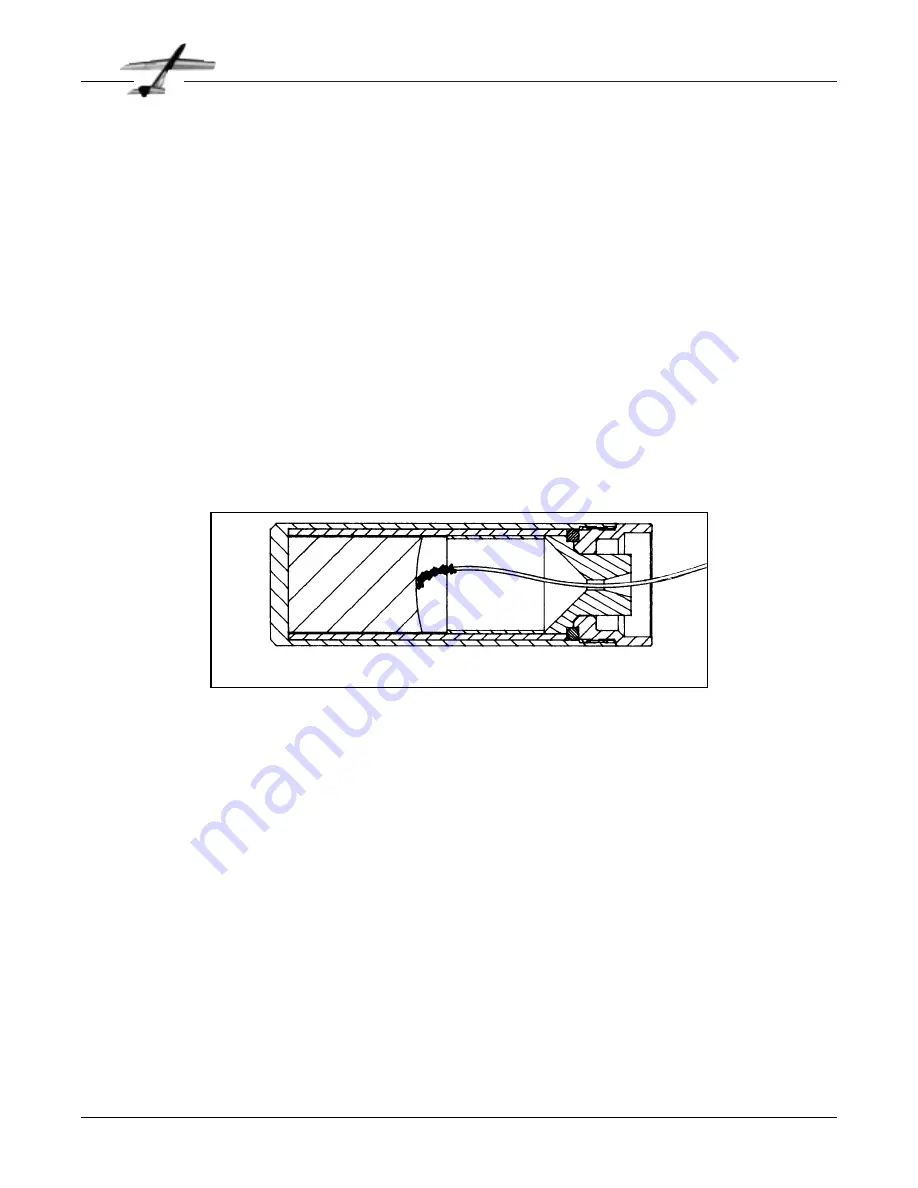
T

YPICAL small rocket motors used in model
rockets are designed to allow the model to

coast for a few seconds, and then deploy a

RMS-RC 32/60-100 Motor with F13-RC reload

Summary of Contents for R/C Aerobatic Glider

Page 1: ...Phoenix Rocket Launched R C Aerobatic Glider Assembly and Operation Manual C O N S U M E R A E R O S P A C E 1991 AeroTech Inc...

Page 2: ...resulting from the handling storage or use of our product The buyer assumes all risks and liabil ities therefrom and accepts and uses AeroTech products on these conditions No warranty either expresse...

Page 3: ...high perfor mance characteristics of Phoenix By interme diate level we mean someone who has previ ously built and successfully flown aileron equipped aerobatic RC models While Phoenix is not difficult...

Page 4: ...y locating the servos away from the center section of the wing where the flight loads are the greatest less structural reinforce ment is required to maintain the designed strength of the overall wing...

Page 5: ...etween 23 to 24 ounces without the rocket motor This is readily achievable with the com ponents in this kit if you take reasonable care in building So build it strong but light Vacuum Bagged Wings THE...

Page 6: ...h water maga zines stereo speakers and scrap metal It really depends on what you have available It isn t worthwhile to buy weights since you could get a vacuum bag system for about the same price Airf...

Page 7: ...dder and aileron controls does make a signif icant improvement in thermalling performance Therefore we do recommend a servo for both rudder and elevator For the remainder of the radio gear we have use...

Page 8: ...about 20 with water and applying it with a small paint brush This will make it eas ier to sand BEGIN construction with the wing We pre fer to build both wings at the same time however you can build th...

Page 9: ...are done WHEN the glue is dry examine the wing skins Generally you will find that one side is smoother and more even than the other This will be the outside of the skin Mark the inside with a felt tip...

Page 10: ...the 1 2 fiberglass reinforcing tape on the inside of the wing skins The location of the tape is shown on the plans The exact posi tion is not too critical Cut the glass tape to the lengths marked on t...

Page 11: ...ight amount of epoxy on the skins the tape should soak up enough turn partial ly clear about a minute after you lay it in place If the tape turns completely clear you used too much resin and your wing...

Page 12: ...apply pressure to the wing to hold everything together while the epoxy cures If you are using a vacuum bag insert the wings and finish sealing the bag Set the entire bag assembly on the appropriate fo...

Page 13: ...s flush with the root and tip ends of the foam cores This does not have to be a particularly neat job since we will be trimming them again later The approximate trim lines are shown on the plans Set t...

Page 14: ...eed to remove the excess balsa until you get to the fiberglass tape Lay a piece of masking tape on the wing with its aft edge aligned with the aft edge of the foam core Add additional strips of tape a...

Page 15: ...em plates are shown on the plans however they will still give you a good idea of the proper shape for several inches each side of the proper location While it probably is not pos sible to get the shap...

Page 16: ...TRIM the two 3 16 x 3 8 x 9 balsa strips to fit in the aileron cutout as shown Glue in place Glue one of the die cut W 1 pieces on each end of the cutout as shown Cut about 1 4 from the end of each a...

Page 17: ...n is cured trim the cloth at the leading and trailing edges CUT a tunnel for the aileron cable Find a 12 long piece of brass tubing of a diame ter large enough to clear your servo connec tors but not...

Page 18: ...s CUT the hinge slots We like to start the slot with a knife and then enlarge it with an X acto 26 saw blade Sand the aileron leading edge to the V shape shown on the plans after the slots are cut We...

Page 19: ...m for use as pushrods Remove the F 5 pod sides from the die cut plywood sheet Typically the surface finish on one side of the plywood is better than on the other Make sure to use the good side of each...

Page 20: ...tered on the boom side to side the back of F 4 should be flush with the back of the pod sides It should canted forward at the bottom to match the back edge of the pod Glue in place with CA You can ma...

Page 21: ...oom provides a very strong fuselage GLUE the pod sides to the pre cut hard balsa nose block Note that the nose block is flush with the top and front of the pod sides Assemble everything together upsid...

Page 22: ...ion is set by the size of the rudder and elevator ser vos you are using Remember to allow for the servo mount rails Cut the hole for the servo leads in F 6 Glue F 6 in place Install the 1 4 x 3 8 serv...

Page 23: ...Use epoxy and apply a fillet along the entire joint Place the wing in position on the fuselage and mark the location of the wing dowel on the leading edge Drill a 3 16 hole through the leading edge T...

Page 24: ...ide the motor mount tube over the casing until it is flush with the front of the cas ing REMOVE the wing Enlarge the hole in the F 9 s with a 11 64 drill Installing the 6 32 blind nut is a bit tricky...

Page 25: ...he boom with CA if you want Wipe off any excess epoxy and allow to cure Remove the motor casing and jig CAREFULLY layout and draw a centerline on the bottom of the tailboom Remove the two F 10 motor s...

Page 26: ...ock loose THE upper surface wing skins need to be trimmed away to clear the motor mount tube Place the wing in position on the fuse lage and approximately mark the area to be removed Begin trimming wi...

Page 27: ...square balsa pushrods that you set aside earlier Bend and cut the two pieces of 1 16 Z bend wire as shown on the plans There is not a lot of room in the back of the tailboom so make the pushrods care...

Page 28: ...zer and the wing Sand the top of the boom until the tail is level Glue the tail in place Make sure the elevator hinge line is perpendicular to the boom centerline The vertical tail is mounted flush wi...

Page 29: ...he voids between the tubing and L 1 Some epoxy will be squeezed out of the channel It can be cleaned off later Check that the rods are parallel before the glue sets Do not glue the aluminum rods in pl...

Page 30: ...the rods before you glue them since it will be difficult to sand later Fill the slots in the L 2 s with epoxy Microbal loons can be used to thicken the epoxy to keep it from running Coat the inside of...

Page 31: ...8 dowel slightly An easy way to do this is to chuck the dowel in an electric drill and sand the ends while it is spinning Insert the dowel in the holes make sure it is cen tered side to side and glue...

Page 32: ...need to drill holes for the elevation screw First note the location of the holes on the plans Install the launcher adapter into the Mantis launcher by flexing the side supports apart and inserting the...

Page 33: ...with iron on plastic film coverings We prepare for covering by sanding the model with progressively finer paper finishing up with 400 grit Carefully vacu um the model to remove the dust Just before c...

Page 34: ...ntroller you need a bat tery The standard 12 Volt rechargeable batter ies used to run model airplanes starters are ideal but a car battery can also be used When you wire the final system we suggest th...

Page 35: ...s an advantage for test flights since you do not have to worry about flying the model to keep it from being hidden behind its own smoke trail The F13 will give you a 400 to 500 foot launch altitude Pr...

Page 36: ...ghts until you are com fortable with the visibility and the perspective It is easy for new pilots to accidentally roll the plane and become disoriented AFTER the motor burns out Phoenix will continue...

Page 37: ...y and then really move out With both of these motors you have to fly Phoenix so your line of sight is not obscured by the motor s smoke trail Aerobatics Phoenix can do any aerobatic maneuver that can...

Page 38: ...ground mount ed devices launching a projectile The only exceptions permitted are rockets flown in accordance with the Safety Code of the National Association of Rocketry or those permanently attached...

Page 39: ...s of 5 feet around the launcher shall be cleared of brown grass dry weeds or other materials that are easily ignit ed 5 The system used to ignite an RG rocket motor shall be remotely controlled and el...

Page 40: ...we use a really high thrust motor then we are likely to leave the wings behind on the launch pad What we need to do is design an appropriate motor that has enough thrust to fly the model while still...

Page 41: ...ll launch a typical Phoenix to about 500 feet in altitude about the same as you would get from a typical hi start launch Your mileage may vary It has an initial thrust of 7 to 8 pounds This gives an i...

Page 42: ...L 1 Die cut plywood 1 8 x 8 x 24 1 per kit F 2 F 1 F 11 F 10 W 1 Die cut balsa 3 32 x 3 x 30 2 per kit V 2 S 2 V 1 S 3 S 3 V 4 V 3 F 12 Tail surface and fuselage parts Cut 1 set from 3 16 x 3 x 30 usi...

Page 43: ...her dowel 3 8 dia x 4 in Other 1 left wing core 1 right wing core 1 1 2 x 13 ft fiberglass tape 1 6 x 20 fiberglass 2 die cut cardboard templates 1 die cut plastic LE template 2 ceramic tile for jet d...

Page 44: ...required 15 long upright 1 required launcher legs Materials 8 feet of 2 x 4 lumber wood screws wood glue TiteBond or equiv Cut 2 x 4 as follows 2 pieces 3 long 1 piece 15 long 2 pieces 4 long Assemble...

Page 45: ...a Fe Oklahoma City OK Futura Home Products Freeport Center Clearfield UT 84016 800 824 2049 part number HM 1203EA You could also try calling aluminum suppliers in your area Other matierials may be sub...

Page 46: ...C O N S U M E R A E R O S P A C E 1955 South Palm St Suite 15 Las Vegas NV 89104 800 752 8018 702 641 2301 Made and Printed in the U S A V 1 1...

Reviews: