background image

13


Copyright © 2013 Alary Design / PhotoShip One LLC   -   

www.PhotoShipOne.com

RC and Joystick Control Connections

The A10 is cable of being controlled  remotely by  an RC controller (Futaba, Spektrum, JR, etc) or a wired 
analog joystick.  We  include  the  wiring harness for this purpose.  Figure  25.   To  install  the  harness first 
disconnect  the  motor  wires  from  the  controller  case.  Be  sure  to  remember  the  orientation  of  the 
connector.  It must be plugged back in the same way later. Next, remove the controller case from the A10 
by removing the four 2mm screws that hold the case to the case cover plate. Then, carefully pull the case 
away from the A10 so that you may access the remote harness port on the controller.  The port is located 
on the main larger square shaped PCB. Figure 26. To better access the port you may remove the smaller 
stacked  PCB  by  carefully  prying it  loose.   Next to  the port  on the larger PCB  you will  see the  markings 
‘Gnd  5v  A1 A0 A2 A3’. Figure 27. The wire harness must  plug into this port.  The harness connector can 
be  inserted  into  a rectangular shaped  opening in the case next  to  the  USB port.   Angle the connector 
sideways  and  it  will  fit  through  the  opening.    Figure  28.  Now  plug in  the  harness  to  the  port.  When 
complete it will look like figure 29.  You may now re-attach the smaller PCB and close up the case.

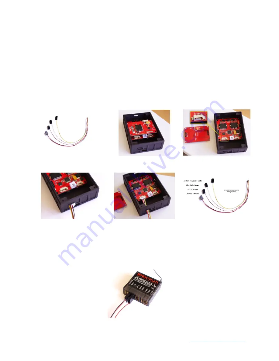
Figure 26. Controller PCBs

Figure 27. Remote Control Port

Figure 28. Wire harness insertion

Figure 29. Controller PCBs

Figure 25. Remote wire harness

Figure 30. Harness Pinout

Now the harness connectors must be plugged into the RC receiver or joystick.  Joystick connections are 
not  covered at this time but will  be in a future version of this manual. For RC receiver control connect as 
shown. Figure 31. The red/black/white lead is plugged into the roll channel. Brown is plugged in to pitch 
channel. Grey and yellow are not used for this purpose. 

Figure 31. Connection to RC Receiver

Summary of Contents for A10

Page 1: ...1 Copyright 2013 Alary Design PhotoShip One LLC www PhotoShipOne com USER MANUAL V1 00 ...

Page 2: ...ching of the voltage source is done at precise intervals to create a rotating electromagnetic field EMF The rotating EMF causes the magnets on the motor rotor to attract and repel to from the EMF This is known as electronic commutation The result is precise motion of the motor output shaft rotor The advantage of brushless motors over brushed motors is greater power output higher efficiency lower e...

Page 3: ...st zoom lenses change length considerably as the focal length gets longer Phoenix A10 works well at focal lengths as long as 200mm Handheld Configuration Assembly One of the most common configurations for Phoenix A10 is the handheld configuration Handheld allows Phoenix A10 to be used in run gun type scenarios as well as used for aerial work from airplane or helicopter Due to A10 being compatible ...

Page 4: ...ount onto the front portion of exposed rods Figure 7 5 Slide the cross rod through the cross rod mount Figure 8 6 install the handles on the ends of cross rod You may angle the handles to suit your comfort Figure 9 Figure 5 15mm rods installed Figure 6 Top handle installed Figure 7 Cross rod mount installed Figure 8 Cross rod installed Figure 9 Handles installed ...

Page 5: ... used along with longer rods The main difference being the Phoenix A10 is mounted on the rods inverted a 15mm rod shoulder pad is installed and a V mount battery is mounted to the rear of the rods for counter balance it is important to note that in this mode the yaw axis setting in the software GUI must be inverted We will discuss that later in the manual Figure 10 Shoulder Configuration Assembled...

Page 6: ...nd roll must be perfect The pan axis balance is less critical balancing is to be accomplished in the steps below Mount the camera to the camera mounting plate Figure 11 Select a slot in the plate that best suits the camera and allows the camera to balance on the tilt axis The center of mass of the camera lens should be directly coincident with the tilt and roll axis rotation points A line drawn th...

Page 7: ...n at any angle after being placed there and letting go If it drops to one side or another the camera needs to be moved left or right There are two methods of moving the camera left right 1 moving the L arm left right relative to the roll motor 2 moving the camera mounting plate left right on the camera mounting tube This is done by loosening the camera mounting plate clamps and sliding the mountin...

Page 8: ...be rubbing against the motor Cameras lighter than 2 0lb 0 9kg may not be able to be perfectly balanced in the yaw axis due to the physical layout geometry of the A10 As previously mentioned it is only important to get the balance as close as possible Figure 17 Yaw motor adjustment Focal Length Changes Most zoom lenses will extend when the focal length is adjusted higher This will cause an imbalanc...

Page 9: ... two different cases depending on which controller is used We use the ArmBGC v3 0 controller and the Flyduino Viacopter controller There is no difference in performance between the two but each requires a different case design due to port button locations on the circuit boards You can identify the case you have by looking at the images below The USB Micro port is on the bottom end of both cases Fi...

Page 10: ...eview the AlexMOS manual and GUI software here http www simplebgc com eng downloads Figure 18 GUI Utility Screenshot Connection of the controller to the GUI is done by a USB Micro port on the bottom of the controller case Figure 19 For more details on tuning the controller with the GUI please check out a great article by Aerial Pixels located here http www aerialpixels com support alexmos brushles...

Page 11: ...ow these steps 1 Orient the IMU in the starting position as shown Figure 23 2 In the GUI go to the Basic tab Look down and to the right for the CalibAcc button Click the button and keep the IMU still for 6 seconds 3 Click the Write button in the GUI 4 Now rotate the IMU 90 degrees and click the CalibAcc button Wait 6 seconds Do NOT click write button from this point forward through the process Wri...

Page 12: ... place If the camera settles down in an off axis attitude in other words if the camera settles in at an odd angle relative to the handles airframe you will need to do a manual camera attitude set routine To complete a manual camera attitude set routine press the mode button four times and immediately grab the camera and hold it in the attitude you want it to remain Hold in this attitude until the ...

Page 13: ... prying it loose Next to the port on the larger PCB you will see the markings Gnd 5v A1 A0 A2 A3 Figure 27 The wire harness must plug into this port The harness connector can be inserted into a rectangular shaped opening in the case next to the USB port Angle the connector sideways and it will fit through the opening Figure 28 Now plug in the harness to the port When complete it will look like fig...

Page 14: ...ng settings are set as shown Figure 32 To control Roll Tilt set as below Source PWM Roll RC_ROLL Pitch RC_PITCH Yaw no input To control Pan Tilt set as below Source PWM Roll no input Pitch RC_PITCH Yaw RC_ROLL Figure 32 RC Mapping GUI Under the RC Control box you may make adjustments to each axis as it pertains to control from the RC transmitter Please refer to the SimpleBGC manual for details on ...

Page 15: ...14 to 25 volts Plus its massive 25mm axles and bearings on all axis ensure that you get slop free tight operation And talk about smooth The A10 effortlessly covers 3 axis pan tilt and roll with solid stabilization at roll rates up to 140 degrees per second and stabilization resolution to 0 1 degrees A10 works with DSLR cameras at focal lengths as long as 200mm for long range stability Totally adju...

Reviews: