background image

UM EN OPC 7015/OPC 7022


8155_en_00 PHOENIX 

CONTACT


Statement of legal authority 

This manual, including all illustrations contained herein, is copyright protected. Use of this manual by 
any third party is forbidden. Reproduction, translation, and public disclosure, as well as electronic 
and photographic archiving or alteration requires the express written consent of Phoenix Contact. 
Violators are liable for damages. 
Phoenix Contact reserves all rights in the case of patent award or listing of a registered design. 
Third-party products are always named without reference to patent rights. The existence of such 
rights shall not be excluded. 


How to contact us 

Internet 

Up-to-date information on Phoenix Contact products and our Terms and Conditions can be found on 
the Internet at: 

http://www.phoenixcontact.com


Make sure you always use the latest documentation. 


It can be downloaded at: 

www.phoenixcontact.net/catalog

 . 


Subsidiaries 

If there are any problems that cannot be solved using the documentation, please contact your 
Phoenix Contact subsidiary.  
Subsidiary contact information is available at 

www.phoenixcontact.com


Published by 


PHOENIX CONTACT GmbH & Co. KG 
Flachsmarktstraße 8 
32825 Blomberg 
DEUTSCHLAND 
T49 - (0) 52 35 - 3-00 
T49 - (0) 52 35 - 3-4 12 00 
 
PHOENIX CONTACT 
P.O. Box 4100 
Harrisburg, PA 17111-0100 
USA 
Phone +1-717-944-1300 
 
Should you have any suggestions or recommendations for improvement of the contents and layout of 
our manuals, please send your comments to 

[email protected]

 .


Summary of Contents for UM EN OPC 7015

Page 1: ...User Manual UM EN OPC 7015 OPC 7022 Panel PC with Touchscreen and Software Keyboard 15 22 Display with the frontsided protection IP65...

Page 2: ...UM EN OPC 7015 OPC 7022 8155_en_00 PHOENIX CONTACT...

Page 3: ...rontsided protection IP65 02 2011 Description UM EN OPC 7015 OPC 7022 Revision 00 This Manual is valid for the Panel PCs OPC 7015 OPC 7022 PxC Description 2700763 OPC 7015 S EXP 2700764 OPC 7015 S W7U...

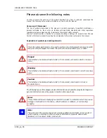
Page 4: ...mbol It is used to alert you to potential personal injury hazards Obey all safety messages that follow this symbol to avoid possible injury or death Danger This indicates a hazardous situation which i...

Page 5: ...g errors in the information cannot be ruled out Phoenix Contact does not offer any guarantees as to the reliability accuracy or completeness of the information All information made available in the te...

Page 6: ...ct us Internet Up to date information on Phoenix Contact products and our Terms and Conditions can be found on the Internet at http www phoenixcontact com Make sure you always use the latest documenta...

Page 7: ...NSTALLATION LAYOUT FOR OPC 7013 16 3 4 EXTERNAL DIMENSIONS OF THE OPC 7015 MODEL 17 3 5 INSTALLATION LAYOUT FOR OPC 7015 18 3 6 EXTERNAL DIMENSIONS OF THE OPC 7022 MODEL 19 3 7 INSTALLATION LAYOUT FOR...

Page 8: ...G THE SERVICE SLOT 35 9 2 1 HDD HARD DISK REPLACEMENT 37 9 3 2 FAN REPLACEMENT 38 9 4 3 WORKING MEMORY RAM REPLACEMENT 39 9 5 4 REPLACING THE LITHIUM BATTERY 40 9 6 5 REPLACING THE FLASH MODULES 41 ni...

Page 9: ...bears sole responsibility for the compliance with any consecutive new technological requirement and adherence to any consecutive new legislatory provision as well as for the observance of their oblig...

Page 10: ...0 55 C only with Flash SSD for storage 30 75 C Temperature for devices OPC 7013 7015 In operation 5 45 C In operation 20 60 C valid only with Flash SSD Automotive HDD or 2 5 Industrial SSD for storage...

Page 11: ...o the instructions in this user manual Pos 9 Datentechnik Allgemeine Hinweise Ausstattungsvarianten Ausstattungsvarianten f r OPC6000 7000 2 mod_1265643750549_6 doc 7192 1 6 EQUIPMENT VERSIONS The sys...

Page 12: ...tion of the device Warning Any leads e g power leads interface cables may only be connected if the device is switched off in order to avoid damaging the device 2 1 OPERATING LOCATION The control syste...

Page 13: ...h load is applied Note The more the battery is exposed to higher temperatures the faster it ages Warning There is an acute risk of explosion should the wrong type of battery be used Warning Do not put...

Page 14: ...or heat source If the device is integrated in a panel casing or similar enclosures you must ensure that no heat accumulation builds up The maximum permissible environmental temperature must never be e...

Page 15: ...UM EN OPC 7015 OPC 7022 PHOENIX CONTACT 8155_en_00 3 2 EXTERNAL DIMENSIONS OF THE OPC 7013 MODEL...

Page 16: ...UM EN OPC 7015 OPC 7022 8155_en_00 PHOENIX CONTACT 3 3 INSTALLATION LAYOUT FOR OPC 7013...

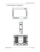
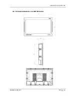
Page 17: ...UM EN OPC 7015 OPC 7022 PHOENIX CONTACT 8155_en_00 3 4 EXTERNAL DIMENSIONS OF THE OPC 7015 MODEL...

Page 18: ...UM EN OPC 7015 OPC 7022 8155_en_00 PHOENIX CONTACT 3 5 INSTALLATION LAYOUT FOR OPC 7015...

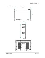
Page 19: ...UM EN OPC 7015 OPC 7022 PHOENIX CONTACT 8155_en_00 3 6 EXTERNAL DIMENSIONS OF THE OPC 7022 MODEL...

Page 20: ...7015 OPC 7022 8155_en_00 PHOENIX CONTACT 3 7 INSTALLATION LAYOUT FOR OPC 7022 Pos 17 Datentechnik Montage Reihenfolge der Montage Reihenfolge der Montage f r OPC 7013 7015 7022 2 mod_1257325957019_6...

Page 21: ...itching on you must wait for at least 5 seconds Note The device is connected with the power supply network by using the enclosed power cable or by using a lead through terminal incl a screw connection...

Page 22: ...evice into the recess created in the described way The tensioners will snap back 3 Please make sure to insert the device carefully into the switching cabinet After that the tensioners will snap back t...

Page 23: ...OPC 7015 OPC 7022 PHOENIX CONTACT 8155_en_00 4 Tensioners must be fastened hand tight Pos 18 Datentechnik Inbetriebnahme Systemmerkmale Inbetriebnahme f r OPC 7013 7015 7022 2 mod_1257326026010_6 doc...

Page 24: ...installed in order to be able to use them Pos 19 Datentechnik Inbetriebnahme Kabelmontage Kabelmontage f r OPC7000 Serie 2 mod_1271079309582_6 doc 7602 4 2 CABLE INSTALLATION The interfaces as well a...

Page 25: ...ansport operating or storage conditions or by improper use or handling e g smoke development from the device etc If any damage is detected the device must be put out of service immediately and protect...

Page 26: ...tness Level 1 Not allocated The configuration of this level can be customised by programming via the soft keyboard programme Level 1 Right mouse key function Shift key SHIFT for activating the second...

Page 27: ...ntations Alphanumeric keys Numeric keys Function key bar Soft keyboard representation zoom in Soft keyboard representation zoom out Note If a function is to be activated which requires pressing two ke...

Page 28: ...Datentechnik Bedienung Status Anzeigen SYS LED SYS LED f r OPC CPC PLC OTC ITC VMT Monitore Serie IPC 5100 5300 5500 1100 1 mod_1204714132162_6 doc 3405 5 4 STATUS INDICATORS SYS LED BICOLOURED Depend...

Page 29: ...e 0 mod_1158923823971_6 doc 547 6 3 USB CONNECTIONS The USB interfaces are used for connecting peripherals with USB connection The interface complies with the USB 2 0 standard PIN NUMBER SIGNAL NAME 1...

Page 30: ...PIN NUMBER SIGNAL NAME 1 TX 2 TX 3 RX 4 NC 5 NC 6 RX 7 NC 8 NC Pos 30 Datentechnik Schnittstellen Serielle Schnittstelle COM RS232 Serielle Schnittstelle COM RS232 f r OPC IPC CPC PLC OTC ITC VMT MSA...

Page 31: ...you d have to ensure that the used device is suitable for industrial environments Warning Connecting or disconnecting external drives during operation is not admissible since it cannot be excluded tha...

Page 32: ...programmes to be installed Hard disk A 2 5 hard disk with at least 40 GB SATA capacity is used On delivery the hard disk is formatted in NTFS format default for Windows XP Note Recommendation for the...

Page 33: ...be reinstalled by using one of the existing interfaces An external keyboard is required for installation 8 1 INSTALLING THE OPERATING SYSTEM The device does not have any integrated CD drive The instal...

Page 34: ...erfectly matches the touch point of your finger you can exit this control menu by pushing OK Pos 35 Datentechnik Software Treiber Installation Softkeyboard Softkeytastatur f r alle Ger t ohne internes...

Page 35: ...that all supply voltages are disconnected from the device 9 1 OPENING THE SERVICE SLOT Remove the four screws holding the service slot on the rear of the device The screws can be removed by using a sc...

Page 36: ...UM EN OPC 7015 OPC 7022 8155_en_00 PHOENIX CONTACT Removing the service slot cover gives you the opportunity of replacing the following components 1 HDD 2 Fan 3 RAM 4 Lithium battery 5 Flash modules...

Page 37: ...DISK REPLACEMENT REMOVAL The pulling aid provided on the HDD should be used for removing the HDD from the device Please pull the HDD carefully out INSTALLATION The HDD must carefully be lowered into t...

Page 38: ...supply cable must be pulled off before replacing the fan REMOVAL Remove the screws holding the fan by using a Tx10 size screw driver The fan can now be lifted from the body and be replaced with a new...

Page 39: ...LACEMENT REMOVAL The RAM component is unlocked and released by pulling both retainer clamps to the outside 1 2 and can be replaced with a new RAM INSTALLATION Put the new RAM into the designated slot...

Page 40: ...LING REPLACING THE BATTERY 2 Now the lithium battery can be removed It must only be replaced by the same battery type The type of battery to be used is Lithium battery 1 2AA 3V e g Phoenix Contact par...

Page 41: ...IX CONTACT 8155_en_00 9 6 5 REPLACING THE FLASH MODULES Note The HDD hard disk must be removed before installing or replacing any of the SSD flash modules REMOVAL Remove the screw s of the spacer bolt...

Page 42: ...ash slot so that the contacts on both sides match and press it carefully down 2 Make sure that the SSD flash module is correctly put in place and that the contacts are properly connected with the SSD...

Reviews: