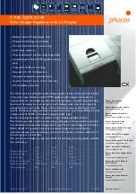


Programmable Solar Charge Controller with Nightlight Function CX10-1.1, CX20-1.1, CX40-1.1
User Manual English, Page 1
Dear Client,
Thank you very much for buying a Phocos product. With your new CX
controller you own a state-of-the art device which was developed
according to the latest available technical standards. It comes with a
number of outstanding features, like:
n
Multifunctional LC display
n
Programmable Low Voltage Disconnect with new ALVD (Adaptive
Low Voltage Disconnect)
n
Sophisticated programmable nightlight function
n
Excess Energy Management (EEM) for better utilization of your solar
system
n
Complete electronic protection
This manual gives important recommendations for installing, using and
programming as well as remedies in case of problems with the controller.
Read it carefully in your own interest and mind the safety and usage
recommendations at the end of this manual.
Description of Functions
n
The charge controller protects the battery from being overcharged
by the solar array and from being deep discharged by the loads. The
charging characteristics include several stages which includes auto-
matic adoption to the ambient temperature.
n
The charge controller adjusts itself automatically to 12V or 24V system
voltage.
n
The pushbutton allows switching the load on and off.
n
The charge controller can be programmed for lighting applications.
n
The controller provides a control output for special loads that make
use of excess energy, like the Phocos SF32E and SF50E Solar Refrigera-
tors. Additionally, it has a serial interface which can be used with an
optional interface adapter (CX-I).
n
The charge controller has a number of safety and display functions.
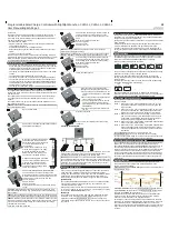
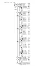
Mounting and Connecting the Charge Controller
The regulator is intended for indoor use only. Protect it from direct
sunlight and place it in a dry environment. Never install it in humid rooms
(like bathrooms).
The regulator measures the ambient temperature to adopt the charg-
ing voltages, therefore it must be installed in the same room as the
battery.
The regulator warms up during operation. It shall be installed on a non
flammable surface only.
REMARK: Connect the controller by following the steps described below
to avoid installation faults.
1
Open the terminal lid.
2
Remove the screws from the strain relief and take
off the strain relief bridges.
3
Mount the controller to the wall with
screws that fit to the wall material.
Use screws with 4 to 5 mm shaft and
max. 9 mm head diameter, no
counter sunk.
Mind that the screws have to carry
also the force applied by the wiring.
Mind also the minimum required
distance to floor and ceiling, this is
necessary for ventilation reasons.
A DIN Rail mounting plate is available
as an accessory (CX-DR2). This allows
mounting the controller on a stan-
dard 35mm DIN rail. Use the screws
supplied with the mounting plate to
fix it to the controller.
> 10cm
> 4
”
> 10cm
> 4
”
4
Connect the wires leading to the battery with
correct polarity. To avoid any voltage on the
wires, first connect the controller, then the battery.
Mind the recommended wire length (min 30 cm
to max approx. 100 cm) and the wire size:
CX10: min 2,5 mm
²
CX20: min 4 mm
²
CX40: min 10 mm
²
Wrong polarity will cause a permanent warning
sound.
WARNING: If the battery is connected with reverse polarity, the load
terminals will also have the wrong polarity. Never connect loads during
this condition!
REMARK: The controller has a built-in voltage drop compensation which
automatically compensates battery wire voltage drops of up to 250 mV.
REMARK: Mind the recommendations of your battery manufacturer. We
strongly recommend connecting a fuse directly to the battery to protect
any short circuit at the battery wiring. The fuse must take the charge
controller nominal current:
CX10: 15A, CX20: 30A, CX40: 50A
5
Connect the wires leading to the solar array with
correct polarity. To avoid any voltage on the
wires, first connect the controller, then the solar
array.
Mind the recommended wire size:
CX10: min 2,5 mm
²
CX20: min 4 mm
²
CX40: min 10 mm
²
REMARK: place positive and negative wire close to each other to
minimize electromagnetic effects.
REMARK: Solar panels provide voltage as soon as exposed to sun light.
Mind the solar panel manufacturer
’
s recommendations in any case.
6
6
To avoid voltage at the load terminal, push the
button to shut off the load output. Connect the
wires leading to the loads with correct polarity.
Mind the recommended wire size:
CX10: min 2,5 mm
²
CX20: min 4 mm
²
CX40: min 10 mm
²
7
Fasten the strain relieves.
8
If you intend to use the Excess Energy
Management output, follow these steps:
a.
Remove the green terminal block in the
terminal compartment and turn it upside
down.
b.
Mount the excess energy signal wires as
shown in the picture beside.
c.
Connect the signal wires to the excess
energy management input of the ap-
propriate load (e.g. Phocos Solar coolers
SF32E, SF50E)
d.
Reconnect the green terminal block to
the CX
9
Close the terminal lid.
Now you have successfully connected your CX
controller.
Grounding the Solar System
Be aware that the positive terminals of the CX controller are connected
internally and therefore have the same electrical potential. If any
grounding is required, always do this on the positive wires.
REMARK: If the CX is used in a vehicle which has the battery negative on
the chassis, loads and solar panels connected to the regulator must not
have an electric connection to the car body. Otherwise the overcharge
protection, the Low Voltage Disconnect and the electronic fuse func-
tion of the controller is short circuited.
Starting up the Controller
Self Test
As soon as the controller is supplied with power either from the battery
or the solar array, it starts a self test routine. This is indicated first by
running LCD bars for approx. 0.5 seconds, and then the firmware version
is displayed in coded symbols for about another second (this is for
service purposes only). Then the display changes to normal operation.
System Voltage
The controller adjusts itself automatically to 12 V or 24 V system voltage.
As soon as the voltage at the time of start-up exceeds 20.0 V, the
controller implies a 24 V system.
If the battery voltage is not within the normal operation range (approx.
12 to 15.5 V or approx. 24 to 31 V) at start-up, a status display according
to the section ERROR DESCRIPTION occurs.
Battery Type
The controller is preset to operate with lead acid batteries with liquid
electrolyte. If you intend to use a VRLA battery (GEL type) you can
adjust the controller in Programming Menu 1 (see back page). The
equalization charge is deactivated then. In case of any doubts consult
your dealer.
Recommendations for Use
The regulator warms up during normal operation. If there is insufficient
ventilation (e.g. in an installation cabinet), the controller limits the solar
charge current to prevent overheating.
The regulator does not need any maintenance or service. Remove dust
with a dry tissue.
It is important that the battery gets fully charged frequently (at least
monthly). Otherwise the battery will be permanently damaged.
A battery can only be fully charged if not too much energy is drawn
during charging. Keep that in mind, especially if you install additional
loads.
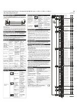
Display Functions
In normal operation mode the controller displays the state of charge
(available energy) of the battery. Any change of the state of charge
(SOC) to a lower status is additionally signalled acoustically.
System conditions are displayed as follows:
25x
5x
3x
2x
1x
Load D isconnect
< 10%
Flashes
10...35%
35...60%
60...80%
> 80%
The percentage corresponds to the available energy until Low Voltage
Disconnect in relation to a fully charged battery.
As long as the solar array supplies enough voltage to charge the
battery, this is indicated by up-moving bars alternately to the state of
charge display.
In normal operation the loads can be switched on and off by pushing
the button. This is indicated in the display:
Load
manually O N
Load
manually O FF
Special conditions are shown in the LC display if the Low Voltage
Disconnect function shuts off the load output or in case of various other
error conditions. See section ERROR DESCRIPTION for details.
Low Voltage Disconnect Function
The controller has 5 different modes to protect the battery from being
deep discharged:
Mode 1 Disconnect at 11.4 V (at nominal load current) up to 11.9 V
(at no load current). Normal operation mode for good bat-
tery protection.
Mode 2 Disconnect at 11.0 V (at nominal load current) up to 11.75 V
(at no load current). Mode with lower disconnection point.
Battery is cycled deeper, this can shorten battery lifetime.
Mode 3 Disconnect at 11.0 V to 12.2 V depending on load current
and previous charging cycles. This adaptive mode leads to
longer lifetime of the battery because it allows recovery of
the battery by full recharge. Maximum battery life.
Mode 4: Disconnect at 11.5 V fixed setting. Appropriate if bypass loads
draw current directly from battery.
Mode 5: Disconnect at 11.0 V fixed setting. Appropriate if bypass loads
draw current directly from battery. Mode with lower discon-
nection point. Battery is cycled deeper, this can shorten bat-
tery lifetime.
The controller is preset to Mode 1 from the factory. Use
Programming Menu 2. to change the setting (see back page).
In case of doubts which mode to choose, consult your dealer because
this has to be evaluated depending on the battery used.
Excess Energy Management Function EEM
The controller provides a built-in excess energy management function.
This function, in combination with especially designed loads (e.g.
Phocos Solar Refrigerators/Coolers SF32E, SF50E), allows to make use of
excess energy which would be lost otherwise because of the over-
charge protection of the battery. A better utilization of the solar system
is the benefit. Also the battery treatment is improved because more
energy comes directly from the solar panel instead of the battery. Ask
you dealer about available loads that can make use of excess energy.
To connect your Excess Energy load with the controller, see picture 8
(signal wires).
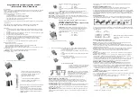
Nightlight Function
The CX controller comes with a sophisticated nightlight function. It
controls the load output at night and is widely programmable.
There are 2 modes available:
DUSK TO DAWN and EVENING/MORNING. The mode can be selected in
Programming Menu 3.
Evening Timing
Light on
Light off
Light off
Light on
M orning Timing
N umber
of hour s
N umber
of hours
or
or
time to
mid of night
time after
mid of night
Mid of night
D usk to D aw n
½
½
If EVENING/MORNING is selected, Programming Menu 5 allows choos-
ing the MORNING timing behaviour, and Programming Menu 4 allows
choosing the EVENING timing behaviour.
Mind that the load output is switched off as soon as the battery has
reached the Low Voltage Disconnect threshold. The Low Voltage
Disconnect has priority above the nightlight function.
“
Mid of night
”
is detected automatically as the middle between dusk
and dawn, no real time setting is required. It may take some days until
the controller has
“
learnt
”
midnight. This method can cause some
inaccuracy but avoids any clock readjustment. The controller
’
s
“
Mid of
night
”
can be different from the real time midnight depending on your
location.
Summary of Contents for CX Series
Page 5: ...Tovární nastavení viz Tabulka ...
Page 7: ......