background image

55BDL4005X/55BDL4007X 

15

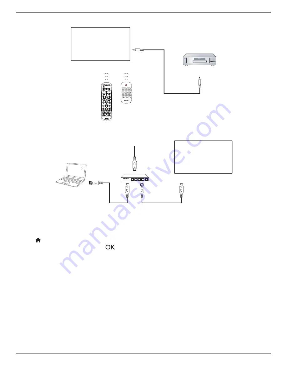
3.6.  IR Pass-through Connection

DVD / VCR / VCD

(DVD / VCR / VCD)

Remote Control

[IR OUT]

[IR IN]

3.7.  Wire-connecting to Network

PC

[RJ-45]

[RJ-45]

ROUTER

INTERNET

Network Settings:

1.  Switch the router on and enable its DHCP setting.
2.  Connect the router to this display with an Ethernet cable.
3.  Press 

[

] HOME


button on the remote control, then select 

Setup

.

4.  Select 

Connect to network

, then press 

[

]

 button.

5.  Wait until this display finds the network connection.
6.  If the “End User License Agreement” window prompts, accept the agreement. 
Note: Connecting with a shielded CAT-5 Ethernet cable to comply with the EMC directive.

Summary of Contents for X Line 55BDL4005X

Page 1: ...www philips com welcome User Manual English Professional Display Solutions X Line 55BDL4005X 55BDL4007X ...

Page 2: ...or drop the display during operation or transportation The eye bolt is for usage in short time maintenance and installation We suggest not to use the eye bolt for more than 1 hour Prolong usage is prohibited Please keep a clear safety area under the display while using the eye bolt Maintenance To protect your display from possible damage do not put excessive pressure on the LCD panel When moving y...

Page 3: ...d be opened only by qualified service personnel Keep the display out of direct sunlight and away from stoves or any other heat sources Remove any object that could fall into the vents or prevent proper cooling of the display s electronics Do not block the ventilation holes on the cabinet Keep the display dry To avoid electric shock do not expose it to rain or excessive moisture When turning off th...

Page 4: ...ns Operation of this equipment in a residential area is likely to cause harmful interference in which case the user will be required to correct the interference at his own expense Changes or modifications not expressly approved by the party responsible for compliance could void the user s authority to operate the equipment Use only an RF shielded cable that was supplied with the display when conne...

Page 5: ...s of standards PN 93 T 42107 and PN 89 E 06251 Electric Magnetic and Electromagnetic Fields EMF 1 We manufacture and sell many products targeted at consumers which like any electronic apparatus in general have the ability to emit and receive electromagnetic signals 2 One of our leading Business Principles is to take all necessary health and safety measures for our products to comply with all appli...

Page 6: ...LUE NEUTRAL N BROWN LIVE L GREEN YELLOW EARTH E 1 The GREEN YELLOW wire must be connected to the terminal in the plug which is marked with the letter E or by the Earth symbol or coloured GREEN or GREEN YELLOW 2 The BLUE wire must be connected to the terminal which is marked with the letter N or coloured BLACK 3 The BROWN wire must be connected to the terminal which marked with the letter L or colo...

Page 7: ...均在 GB T 26572规定的限量要求以下 X 表示该有害物质至少在该部件的某一均质材料中的含量超出GB T 26572规定的限量要求 上表中打 的部件 应功能需要 部分有害物质含量超出GB T 26572规定的限量要求 但符合欧盟 RoHS法规要求 属于豁免部分 备注 上表仅做为范例 实际标示时应依照各产品的实际部件及所含有害物质进行标示 10 环保使用期限 此标识指期限 十年 电子电气产品中含有的有害物质在正常使用的条件下不会发生外泄或突变 电 子电气产品用户使用该电子电气产品不会对环境造成严重污染或对其人身 财产造成严重损害的期限 废弃电器电子产品回收处理管理条例 提示性说明 为了更好地关爱及保护地球 当用户不再需要此产品或产品寿命终止时 请遵守国家废弃电器电子产品 回收处理相关法律法规 将其交给当地具有国家认可的回收处理资质的厂商进行回收处理 不当利用或 者处置可能会对环境和人类...

Page 8: ...овою Кабінету Міністрів України від 3 грудня 2008 1057 End of Life Disposal Your new Public Information Display contains materials that can be recycled and reused Specialized companies can recycle your product to increase the amount of reusable materials and to minimize the amount to be disposed of Please find out about the local regulations on how to dispose of your old display from your local Ph...

Page 9: ...ting For more information on the ENERGY STAR program refer to energystar gov Restriction on Hazardous Substances statement India This product complies with the E Waste Management Rules 2016 CHAPTER V rule 16 sub rule 1 Whereas New Electrical and Electronic Equipment and their components or consumables or parts or spares do not contain Lead Mercury Cadmium Hexavalent Chromium polybrominated bipheny...

Page 10: ...method of disposal of the used battery According to EU directive 2006 66 EC the battery can t be disposed improperly The battery shall be separated to collect by local service Após o uso as pilhas deverão ser entregues ao estabelecimento comercial ou e ou baterias rede de assistência técnica autorizada Information for EAC Month and year of manufacturing please refer information in Rating label Nam...

Page 11: ... speakers 13 3 4 Connecting Multiple Displays in a Daisy chain Configuration 14 3 4 1 Display control connection 14 3 4 2 Digital video connection 14 3 5 IR connection 14 3 6 IR Pass through Connection 15 3 7 Wire connecting to Network 15 4 Operation 16 4 1 Watch the Connected Video Source 16 4 2 Change Picture Format 16 4 3 Play multimedia files via Local Area Network 16 4 3 1 Network settings 16...

Page 12: ... RS232 Cable RS232 Daisy Chain Cable Edge Alignment Kit 1 Edge Alignment Kit 2 IR Sensor Cable IR Cable DVI Cable Edge Alignment Pin AC Switch Cover HDMI Cable Wire Clamper Gap Mylar Differences according to regions Display design and accessories may differ from those illustrated above NOTES For all other regions apply a power cord that conforms to the AC voltage of the power socket and has been a...

Page 13: ...ures could result in damage to the equipment or injury to the user or installer Product warranty does not cover damage caused by improper installation 4 For the wall mounting kit use M6 mounting screws with a length 10 mm longer than the thickness of the mounting bracket and tighten them securely 1 4 1 VESA Grid 55BDL4005X 400 H x 400 V mm 55BDL4007X 400 H x 400 V mm Caution To prevent the display...

Page 14: ... in Portrait Orientation This display can be installed in portrait orientation Rotate the display 90 degrees counterclockwise based on the back view The PHILIPS LOGO should be on the LEFT side when facing the backside of the display 90 90 ...

Page 15: ... any damage to the product if the installation is not performed by a professional technician Use the provided thumb screw for an easy installation of the edge alignment kit Use the Edge Alignment Kit 1 for four adjacent displays Display 1 Display 2 Display 3 Display 4 Use the Edge Alignment Kit 2 for two adjacent displays Display 1 Display 2 Note When installing the edge alignment kit please consu...

Page 16: ...ishing Kit Top Bottom EFK5564 Edge Finishing Kit Left Right EFK5534 Edge Finishing Kit Top Bottom EFK5534 Edge Finishing Kit Top Bottom EFK5534 Edge Finishing Kit Top Bottom EFK5564 Edge Finishing Kit Left Right EFK5564 Edge Finishing Kit Left Right EFK5564 Edge Finishing Kit Left Right For more detail information please check the instruction guide in the package of kit ...

Page 17: ...Move the selected item one level up while the OSD menu is On 7 button Move the selected item one level down while the OSD menu is On 8 MENU button Return to the previous menu while the OSD menu is On This button can also be used to activate the OSD menu when the OSD menu is Off 9 Remote control sensor and power status indicator Receives command signals from the remote control Indicates the operati...

Page 18: ...UT DVI or VGA video output 9 DisplayPort IN 10 DisplayPort OUT DisplayPort video input output 11 VGA IN D Sub VGA video input 12 COMPONENT IN BNC Component YPbPr video source input 13 Y CVBS Video source input 14 PC LINE IN Audio input for VGA source 3 5mm stereo phone 15 SPEAKER SWITCH Internal speaker on off switch 16 AUDIO IN Audio input from external AV device RCA 17 AUDIO OUT Audio output to ...

Page 19: ...y information about current activity 7 NAVIGATION buttons Navigate through menus and choose items 8 button Confirm an entry or selection 9 BACK button Return to the previous menu page or exit from the previous function 10 MUTE button Press to turn the mute function on off 11 COLOR buttons Choose tasks or options 12 NUMERIC buttons Enter text for network setting and set up ID for ID mode 13 FORMAT ...

Page 20: ...hin 10 seconds will exit the ID Mode 3 If a wrong button is pressed wait 1 second after the red LED lights off and then lights up again then press the correct digits again 4 Press ENTER button to confirm The red LED blinks twice and then lights off NOTE Press NORMAL button The green LED blinks twice indicating the display is in normal operation It is necessary to set up the ID number for each disp...

Page 21: ...e of flammable liquid or gas and a battery subjected to extremely low air pressure that may result in an explosion or the leakage of flammable liquid or gas Note Remove the batteries from the battery compartment when not using for an extended period of time 2 3 4 Handling the remote control Do not drop or apply shock to the remote control Do not allow any liquid to get inside the remote control If...

Page 22: ...D 3 1 1 Using COMPONENT video input DVD VCR VCD COMPONENT Out YPbPr Audio Out AUDIO IN COMPONENT IN YPbPr PC LINE IN SPEAKER SWITCH Pr Pb Y CVBS AUDIO IN AUDIO OUT 3 1 2 Using Video Source input Y CVBS IN DVD VCR VCD CVBS OUT Audio Out AUDIO IN PC LINE IN SPEAKER SWITCH Pr Pb Y CVBS AUDIO IN AUDIO OUT ...

Page 23: ...3 2 Connecting a PC 3 2 1 Using VGA input PC VGA IN VGA AUDIO IN VGA Out D Sub 15 pin Audio Out PC LINE IN SPEAKER SWITCH Pr Pb Y CVBS VGA IN 3 2 2 Using DVI input DVI IN PC VGA AUDIO IN Audio Out DVI IN DVI OUT DP IN DP OUT PC LINE IN SPEAKER SWITCH Pr Pb Y CVBS VGA IN DP OUT PC LINE IN SPEAKER SWITCH Pr Pb Y CVBS VGA IN DVI Out ...

Page 24: ...I IN PC HDMI1 IN HDMI2 IN DVI IN DVI OUT DP IN DP OUT Pr Pb VGA IN 3 2 4 Using DisplayPort input 3 3 Connecting Audio Equipment 3 3 1 Connecting external speakers VGA IN EXT SPK TERMINAL SPEAKER SWITCH AUDIO IN AUDIO OUT IR IN IR OUT SPDIF OUT External speakers ...

Page 25: ...nect the RS232C OUT connector of DISPLAY 1 to the RS232C IN connector of DISPLAY 2 DISPLAY 1 DISPLAY 2 PC RS 232C IN RS 232C RS 232C OUT RS 232C IN 3 4 2 Digital video connection Connect the DP OUT connector of DISPLAY 1 to the DP IN connector of DISPLAY 2 PC DP IN DP DP OUT DP IN DISPLAY 1 DISPLAY 2 3 5 IR connection DISPLAY 1 IR IN External IR Receiver NOTE This display s remote control sensor w...

Page 26: ...on and enable its DHCP setting 2 Connect the router to this display with an Ethernet cable 3 Press HOME button on the remote control then select Setup 4 Select Connect to network then press button 5 Wait until this display finds the network connection 6 If the End User License Agreement window prompts accept the agreement Note Connecting with a shielded CAT 5 Ethernet cable to comply with the EMC ...

Page 27: ...l Plug and Play uPnP router Optional A LAN cable that connects your display to your home network A media server running on your computer Appropriate settings on your computer firewall to allow you to run the media server 4 3 1 Network settings 1 Connect your display and the computer to the same home network Refer to the connection diagram as shown below 2 Switch your PC and router On Single displa...

Page 28: ...ia Renderer D Network name Clear Internet memory Cancel Done Clear xxxxxxxx 4 Press HOME button and press SOURCE button Then choose Network and press button 5 On your PC go to Network and Sharing Center and click Choose homegroup and sharing options 6 Check the media formats Then click Choose media streaming options 7 Go to Advanced sharing settings and click Turn on network discovery 8 Go to the ...

Page 29: ...or forward press or button press repeatedly to toggle between different speeds To stop the music press button Music options While you play the music press OPTIONS button then press button to choose an option Shuffle Songs are played in a randomized order Repeat Choose Repeat to play a track or an album repeatedly or choose Play once to play a track once Note To view information about a song for ex...

Page 30: ... c c c c c c c c c c c c c c c c c c c c c c c c c c c c c c c c c c c c c c c c c c c c c co o o o o o o o o o o o o o o o o o o o o o o o o o o o o o o o o o o o o o o o o o o o o o o o o o o o o o o o o o o o o o o o o o o o o o o o o o o o o o o o o o o o o o o o o om m m m m m m m m m m m m m m m m m m m m m m m m m m m m m m m m m m m m m m m m m m m m m m m m m m m m m m m m m m m m m m m m...

Page 31: ...ettings Advanced Help Picture style Choose a predefined picture setting Backlight Adjust the brightness of this display s backlight Colour Adjust the colour saturation of the picture Sharpness Adjust the sharpness of the picture Noise reduction Choose the amount of noise reduction for the picture MPEG artifact reduction Smoothen transitions and haziness in the digital picture Picture enhancement F...

Page 32: ...ut line out Adjust audio output volume Advanced Access advanced settings to enhance your audio experience Auto volume leveling Enable the reduction of sudden volume changes Speaker settings Turn on or off the internal speakers Clear sound Enhance sound quality Audio out format Choose the type of audio output through the digital audio output connector HDMI only Audio out delay Automatically synchro...

Page 33: ...ower on delay time in seconds for each display to reduce the power load RS232 Routing Select the control port RS232 Select RS232 Control LAN RJ 45 Select LAN control IR Select the operation mode of the remote control when multiple displays are connected via an RS232C connection IR Control Select the operation mode of remote control when multiple displays are connected via an RS232C connection Norm...

Page 34: ...d from dealer Picture Sound Tiling Network General settings Advanced Help Status Activate Enable H monitors V monitors Position Frame comp Frame comp H Frame comp V Switch on delay RS232 Routing Auto ID Tiling tool 1 Enter activate menu Picture Sound Tiling Network General settings Advanced Help Status Activate 2 Enter activate key in OSD Cancel Done Clear _ 3 Press OK button and an on screen keyp...

Page 35: ...n multiple sets of display are connected Monitor ID number range is between 1 and 255 The default setting is 1 Eco mode This setting allows you to reduce the power consumption of the display automatically Note If Eco mode is set to Normal you cannot reset it to the default setting which is low power standby from the Factory reset menu However you can still set the Eco mode to low power standby man...

Page 36: ... Tiling Network General settings Advanced Help Menu language Monitor Group Monitor ID Eco mode Auto search Clock Scheduling Sleep timer OneWire Local KB lock RC lock 1 You can set up to 7 schedules Go to Status and choose On Status Source On time Off time Repeat modes Playlist setting Off On Schedule 1 Schedule 2 Schedule 3 Schedule 4 Schedule 5 Schedule 6 Schedule 7 2 Go to Source and select the ...

Page 37: ...l keyboard functions except the and buttons Lock but power Disable all keyboard functions except the button Lock all expect volume and power Disable all keyboard functions except the and buttons RC lock Choose to enable or disable the button function of the remote control Unlock Enable the remote control function Lock all Lock all remote control functions Lock but volume Disable all remote control...

Page 38: ...isplayPort Ver to 1 2 to support MST Multi Stream Transport Notes If the display shows a black screen or works abnormally under DisplayPort source please switch to 1 1a and turn AC off and on For DP daisy chain application please select the same DP version for all PD Cooling Fan Select On to turn on the cooling fan permanently Select Auto to turn on off the cooling fan according to the display s t...

Page 39: ... 25p 30p 50p 60p 60i 30 MVC 1920x1080i field rate 50 60Hz 1920x1080p frame rate 24 25 30Hz 1280x720p frame rate 50 60Hz 30 ts m2ts mts AVCHD MPEG 2 1920x1080 25p 30p 50i 60i 30 MPEG 1 L1 L2 MPEG 1 2 2 5 L3 AAC HE AAC v1 v2 MPEG 4 ASP 1920x1080 25p 30p 50i 60i 30 H 264 1920x1080 25p 30p 50p 60p 60i 30 ts m2ts mts AVCHD MVC 1920x1080i field rate 50 60Hz 1920x1080p frame rate 24 25 30Hz 1280x720p fra...

Page 40: ... Maximum Resolution Frequency Max Bit Rate Audio codec jpg jpeg JPEG baseline color mode 444 size 32768x16128 color mode 422v size 16384x16128 color mode other not support bmp BMP 4096x3072_4bit 2730x2500_8bit 2048x1536_16bit 1500x1200_32bit png PNG 4096x3072_4bit 2730x2500_8bit 2048x1536_16bit 1500x1200_32bit gif GIF 4096x3072_4bit 2730x2500_8bit 2048x1536_16bit 1500x1200_32bit NOTES Sound or vid...

Page 41: ...80 720 50 Hz 74 25 MHz 16 9 Normally DVB Mode 60 Hz 1080i 1920 1080 25 Hz 74 25 MHz 16 9 Normally ATSC Mode 30 Hz 1080p 1920 1080 50 Hz 148 5 MHz 16 9 Normally ATSC Mode 60 Hz The PC text quality is optimum in HD 1080 mode 1920 x 1080 60Hz Your PC display screen might appear different depending on the manufacturer and your particular version of Windows Check your PC instruction book for informatio...

Page 42: ... A pixel or picture element is composed of three sub pixels in the primary colors of red green and blue Many pixels together form an image When all sub pixels of a pixel are lit the three colored sub pixels together appear as a single white pixel When all are dark the three colored sub pixels together appear as a single black pixel Other combinations of lit and dark sub pixels appear as single pix...

Page 43: ...EFECTS OF ALL TYPES 12 Note 1 or 2 adjacent sub pixel defects 1 dot defect 8 7 MURA Dark spots or patches may occasionally appear on some liquid crystal display LCD panels This is known within the industry as Mura which is a Japanese term for unevenness It is used to describe an irregular pattern or area in which uneven screen uniformity appears under certain conditions Mura is a result of the det...

Page 44: ...y treated Wipe the surface gently using only a cleaning cloth or a soft lint free cloth If the surface becomes dirty soak a soft lint free cloth in a mild detergent solution Wring the cloth to remove excess liquid Wipe the surface of the display to remove dirt Then use a dry cloth of the same type to dry Do not scratch or hit the surface of the panel with fingers or hard objects of any kind Do not...

Page 45: ...e set incorrectly to underscan 3 If the image exceeds the screen size Scan Mode may need to be set to Underscan Use the Zoom mode or Custom zoom function in the Screen menu to fine tune display geometry and time frequency parameter Can hear sound but no picture Source signal cable is connected improperly Make sure that both video inputs and sound inputs are correctly connected Can see picture but ...

Page 46: ...nt Warranty period for PHILIPS signage display is listed as below for areas not covered in this table please follow their warranty statement Region Warranty Period USA Canada 3 years China 1 year Asia Pacific 3 years Europe 3 years Brazil 3 years ...

Page 47: ...m Phone jack x 2 RS232 in RS232 out IR Input Output 3 5mm Phone jack x 2 IR in IR out RJ 45 Input Output RJ 45 Jack x 2 8 pin 10 100 LAN Port HDMI Input HDMI Jack x 2 Type A 18 pin Digital RGB TMDS Video Audio MAX Video 720p 1080p 3840 x 2160 30 Hz Audio 48 KHz 2 Channel L R Supports LPCM only DVI D Input DVI D jack Digital RGB TMDS Video VGA Input D Sub Jack x 1 15 pin Analog RGB 0 7V p p 75Ω H C...

Page 48: ... mm D Handle Weight 24 87 Kg 24 87 Kg Gross Weight 34 3 Kg 34 3 Kg Energy Efficiency Class A B On Mode Power Consumption W 110 W 113 W Annual Energy Consumption kWh 161 kWh 165 kWh Standby Power Consumption W 0 50 W 0 50 W Off Mode Power Consumption W 0 W 0 W Display Resolution Pixels 1920 x 1080 1920 x 1080 Network Standby W 2W 2W Environmental Condition Item Specifications Temperature Operationa...

Page 49: ...sponsibility of Top Victory Investments Ltd and Top Victory Investments Ltd is the warrantor in relation to this product Philips and the Philips Shield Emblem are regis tered trademarks of Koninklijke Philips N V and are used under license Specifications are subject to change without notice Version V1 00 2021 03 15 ...

Reviews: