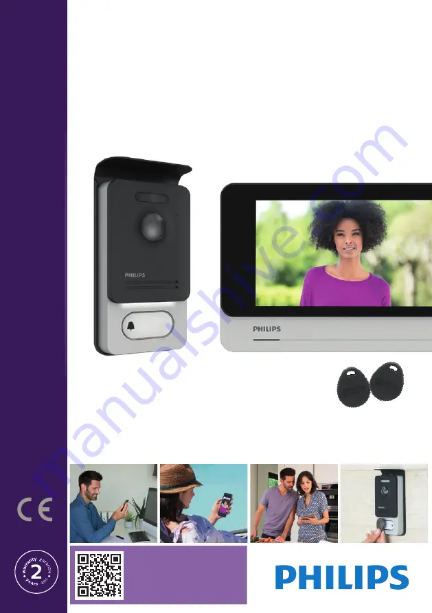
background image

Welcome

Eye 

Connect

DES9900VDP - 531002

Welcome

Eye 

Touch

DES9700VDP - 531001

05/2020

V4

Scan me  

to find out about our products

Flashez-moi


pour découvrir nos produits

FR -Notice téléchargeable sur philips.com

GB - Downloadable instructions at phillips.com

D - Anleitung kann auf philips.com heruntergeladen werden

NL - De handleiding kan gedownload worden op philips.com

PL - Instrukcja do pobrania na philips.com

IT- Il manuale è disponibile anche su www.philips.com.

ES - Manual que puede descargar en philips.com

PT - Manual de instruções disponível no site philips.com

N

o

tic

e d’utilisa

tion / U

ser

 manual

Summary of Contents for WelcomeEye Connect

Page 1: ...hilips com GB Downloadable instructions at phillips com D Anleitung kann auf philips com heruntergeladen werden NL De handleiding kan gedownload worden op philips com PL Instrukcja do pobrania na philips com IT Il manuale è disponibile anche su www philips com ES Manual que puede descargar en philips com PT Manual de instruções disponível no site philips com Notice d utilisation User manual ...

Page 2: ...nitor 4 Installing the main or additional intercom panel 5 Installing a camera optional 6 MONITOR INTERFACE p 9 A Monitoring function and response to a call B Intercom function C Settings D Photo album E Video album 7 USER GUIDE p 14 8 SMARTPHONE APPLICATION p 15 9 TECHNICAL CHARACTERISTICS p 21 10 ACCESSORIES p 23 11 FAQ p 23 12 TECHNICAL ASSISTANCE WARRANTY p 27 13 SAFETY PRECAUTIONS p 27 14 FCC...

Page 3: ...y an authorised technician Safety precautions To ensure the safe operation of the system installers users and technicians must follow all the safety procedures described in this manual Specific warnings and warning symbols are marked on the components where necessary 2 CONTENTS OF THE KIT 5 Plug in power supply 1 7 monitor 2 Wall bracket 3 Intercom panel 4 5 RFID badges 2 user badges grey 1 admin ...

Page 4: ...Eye technology allows you to share the intercom panel between 2 families Each family can own up to three monitors The system can operate up to one camera and two intercom panels per family To get the most out of your intercom please read this instruction manual carefully 4 NOMENCLATURE Monitor Touch screen Power supply terminal block Terminal block for connection to the intercom panel and accessor...

Page 5: ...IP44 20V 110mA RFID 125kHz Avidsen 19 avenue Marcel Dassault 37200 TOURS FRANCE DES 9901 VDP 5 1 0 0 6 3 1 2 3 4 5 6 1 2 7 8 1 2 1 2 DES 9901 VDP 5 1 0 0 6 3 Made in P R C IP44 20V 110mA RFID 125kHz Avidsen 19 avenue Marcel Dassault 37200 TOURS FRANCE DES 9901 VDP 5 1 0 0 6 3 1 2 3 4 5 6 1 2 7 8 1 2 1 2 DES 9901 VDP 5 1 0 0 6 3 Made in P R C IP44 20V 110mA RFID 125kHz Avidsen 19 avenue Marcel Dass...

Page 6: ...ase their section a Connecting the videophone monitor intercom panel and camera Wires to be used two wires 0 75mm2 with 80m length or two wires 1 5mm2 with 120m length Make sure to connect the wires in accordance with one of the wiring diagrams depending on the desired configuration Refer to the label stuck to the back of the monitor and the back of the intercom panel Configure the switches on the...

Page 7: ...ong beeps confirm the activation of the programming mode 2 Swipe all user badges grey to be activated one short beep confirms the programming of every badge presented 3 Once all of the badges have been programmed wait 10 seconds One long beep confirms the end of the programming process 3 Remove one or more user badges 1 Swipe the badge red 4 long beeps confirm the activation of the programming mod...

Page 8: ...4 7 5 6 3 1 Position the wall bracket so that the screen of the monitor is approximately 1 60m above the ground 2 Mark the location of the holes using the U bolt 3 Drill 4 Use pegs adapted to the bracket those supplied are suitable for solid walls 5 Attach the wall bracket 6 Connect the two intercom panel wires and the two power supply wires in accordance with the wiring diagram 7 Position the mon...

Page 9: ...com panel 2 Tip the intercom panel cover forward 3 The intercom s lens should be approximately 1 60m above the ground 4 Mark the locations 5 Drill 6 Use pegs adapted to the nature of the support the screws supplied are suitable for solid walls 7 Connect the two wires from the monitor and if necessary connect the electric strike plate and the gate see section 1 Wiring Configure the switches at the ...

Page 10: ...one vinegar odour 5 Installing a camera optional Connect the wires in accordance with the wiring diagram Choose a suitable place to install the camera Ensure that nothing gets in the way of the installation Screw the wall section with the screws provided for solid walls Point the camera in the desired direction and tighten the retainer screw Configure the monitor s On 6 MONITOR INTERFACE Main Menu...

Page 11: ...pen the gate 5 To take a photo or video in accordance with the settings selected B Intercom function 1 2 Function only valid if an additional monitor is connected and the parameters are set correctly 1 To exit the function 2 To call the family s other monitors to respond when receiving a call from another monitor or to hang up C Settings The settings menu consists of three pages for the WelcomeEye...

Page 12: ...ng mode 4 De activation of silent mode This function turns off the monitor ringtone for a certain period snooze etc The monitor LEDs will continue flashing to indicate a call a b c a activate On deactivate Off the monitor s silent mode b Time when the ringtone will be deactivated c Time when the ringtone will be reactivated 5 Answering system function only on WelcomeEye Connect valid if video mode...

Page 13: ...ttings a b c d e a Choice of ringtone during a call from intercom panel 1 b Choice of ringtone during a call from intercom panel 2 only if an additional intercom panel has been configured c Choice of ringtone during an intercom call only if an additional monitor has been configured d Volume settings for the monitor ringtone e Volume settings for the monitor loudspeaker during communication 8 Image...

Page 14: ...ering system function options configuration audio settings image settings Wi Fi time and date The photos and videos recorded are saved D Photo album To access the album of recorded photos The figure in the red circle indicates the number of unread photos time and date photo was taken Click on it to view the photo To delete one or several photos Click on the waste bin then select the photos to be d...

Page 15: ...D card is inserted Otherwise they are stored on the micro SD card Note the photos saved in the internal memory may not be copied onto a memory card You can also choose the video recording In this case a video with sound is recorded This function requires a micro SD card Videos will only be recorded on your micro SD card The recording time can be adjusted 10 20 or 30 seconds When there is a recorde...

Page 16: ...e Philips WelcomeEye application onto your smartphone From the Apple store or Play store 2 From the monitor go to then and activate Wi Fi 3 Go to and the following menu appears Note If the icon does not appear on the second line reset Wi Fi by clicking on then wait until the icon appears approximately 30s 4 From the WelcomeEye application click on to add a device ...

Page 17: ...Eye Connect Touch 05 20 5 Android Click on new device and then next 6 The UID of your monitor should appear Click on it Choose the box to which you wish to connect your monitor enter its password and click on next ...

Page 18: ...new device and then next Exit the application and go to the Wi Fi settings of the smartphone Log in to the Wi Fi starting with UIDcg Return to the application and click on next Enter the name of your network and its password then click on next Show password ...

Page 19: ... gate control Click on Save Your videophone is now connected to the Wi Fi network and your smartphone can receive calls Add a smartphone to a connected videophone 1 Download the Philips WelcomeEye application onto your smartphone from the Apple App Store or Google Play Store Warning deactivate the smart Wi Fi network mode on the smartphone if it is activated 2 From the WelcomeEye application click...

Page 20: ...sked for the password every time you wish to open your electric strike plate or gate from the application Warning If you choose 1 for the channel number you may only control the electric strike plate Click on Save 6 Your smartphone can now receive calls from your videophone Interface function Contains the different devices and enables switching to monitoring mode Adding a device Click on the pictu...

Page 21: ...o Reduces the quality of the video 1 bar or only records the sound 0 bar if band width is limited For optimum performance minimum throughput must be 40 kB s Full screen mode Open the electric strike plate or gate default password 1 2 3 4 Note the number of doors must be set to 2 to control the opening of the gate Press and hold to talk to the visitor To delete the recordings Contains the recording...

Page 22: ...CHARACTERISTICS Monitor ref 538102 WelcomeEye Connect ref 538101 WelcomeEye Touch 2 wires 7 touch screen Resolution 800 x 480 Class 10 micro SD card up to 32GB not supplied Wi Fi 2 4 GHz IEEE 8111 b g n WelcomeEye Connect only Radio power emitted 18 dB maximum Current consumption 550mA Connect 470mA Touch Power consumption 13 2W Connect 11 3W Touch 6 ringtones 85dB Dimensions 142 h x 210 l x 15 d ...

Page 23: ...11 1W 6 ringtones 85dB Dimensions 142 h x 210 l x 15 d mm WelcomeEye AddCompact additional monitor ref 531005 2 wires 4 3 screen Resolution 480 x 272 Current consumption 400mA Power consumption 9 6W 6 ringtones 85dB Dimensions 116 h x 146 w x 16 d mm WelcomeEye Outdoor Additional intercom panel ref 531006 C MOS colour sensor 900TVL Viewing angle H130 V 90 Night vision white LEDs Strike plate contr...

Page 24: ...the www philips com website for more information 11 FAQ Failure Cause Solution The monitor does not turn on The monitor is not connected to a power source Verify that the power supply is properly connected and turned on Check the polarity on the monitor or at the power supply output Poor connection or short circuit on the line Resolve the connection problem Does not work when installed for the fir...

Page 25: ...rcom panel for single family use Energy saving mode activated page 12 Poor picture and or sound Environment Check that the wires used are the correct size and that the videophone s connection wires are not in the same sheath as the 230VAC wires Purple picture Connection The connection cable must not be tangled Image is too bright Camera position Do not expose the lens of the camera directly to sun...

Page 26: ...fy that the additional monitor is connected to 1 and 2 of the intercom panel for single family operation The additional intercom panel is not working Configuration Verify the position of switch 1 on the panels page 6 it must be different Don t forget to turn the power off for five seconds to activate the new settings Configuration menu of the monitors Verify that the monitors are valid BOTH of the...

Page 27: ...nfiguration In application settings verify that code verr 2 Reminder the command can only be sent if a conversation via the intercom is ongoing The strike plate is not controlled via the monitor The strike plate or electric lock that you are ordering must have a mechanical memory The strike plate current cannot exceed 1 1A Connect it directly to terminals 7 and 8 at the back of the intercom panel ...

Page 28: ...re brush or other sharp tool etc for cleaning The till receipt or invoice is your proof of purchase date If necessary the contacts and opening hours of our technical assistance centres are available on the www philips com website WARRANTY CARD Mr Mrs Phone number Address E mail Date of purchase DD MM YYYY Dealer Dealer Phone Dealer address Serial number PHI 1031 Important Please keep this warranty...

Page 29: ...wer grid Keep a minimum distance around the device to guarantee sufficient ventilation Ventilation should not be blocked by covering the ventilation opening with an object such as a newspaper tablecloth or curtain etc No open flame source such as a burning candle must be placed on the device Respect the product s operating temperature The device must not be exposed to liquid flow or splashing Do n...

Page 30: ...ust only be installed and used indoors D Dieses Symbol zeigt an dass das Gerät nur innen installiert und verwendet wird NL Dit symbool betekent dat het apparaat alleen binnen mag worden geïnstalleerd en gebruikt PL Ten symbol wskazuje iż urządzenie przeznaczone jest wyłącznie do montażu i użytku wewnętrznego IT Questo simbolo indica che l apparecchio si installa e si utilizza unicamente all intern...

Reviews: