AV (A
UDIO
/V
IDEO
) I
NPUT
C
ONNECTION
4
L/Mono
Monitor out
VIDEO
S-VIDEO
AV1 in
Y
Pb
Pr
AV2 in
AUDIO
R
COMPONENT VIDEO INPUT
AUDIO OUT
R L
S-VIDEO
OUT
ANT/CABLE
OUT
VIDEO
OUT
3
AUDIO OUT
R L
S-VIDEO
OUT
ANT/CABLE
OUT
VIDEO
OUT
3
4
5
7
1
2
4
2
1
5
7
Audio and video cables are not sup-
plied with the TV, but are available
from Philips or electronics retailers.
H
ELPFUL
H
INT
Audio In
(Red and
White)
VCR Two (or accessory
device) (Equipped with
Video and Audio Output Jacks)
Video In
(Yellow)
Back of VCR
Back of TV
AV
1
Connection
AV2 Connection
VCR One (or
accessory device) (Equipped
with Audio and Video Output
Jacks)
T
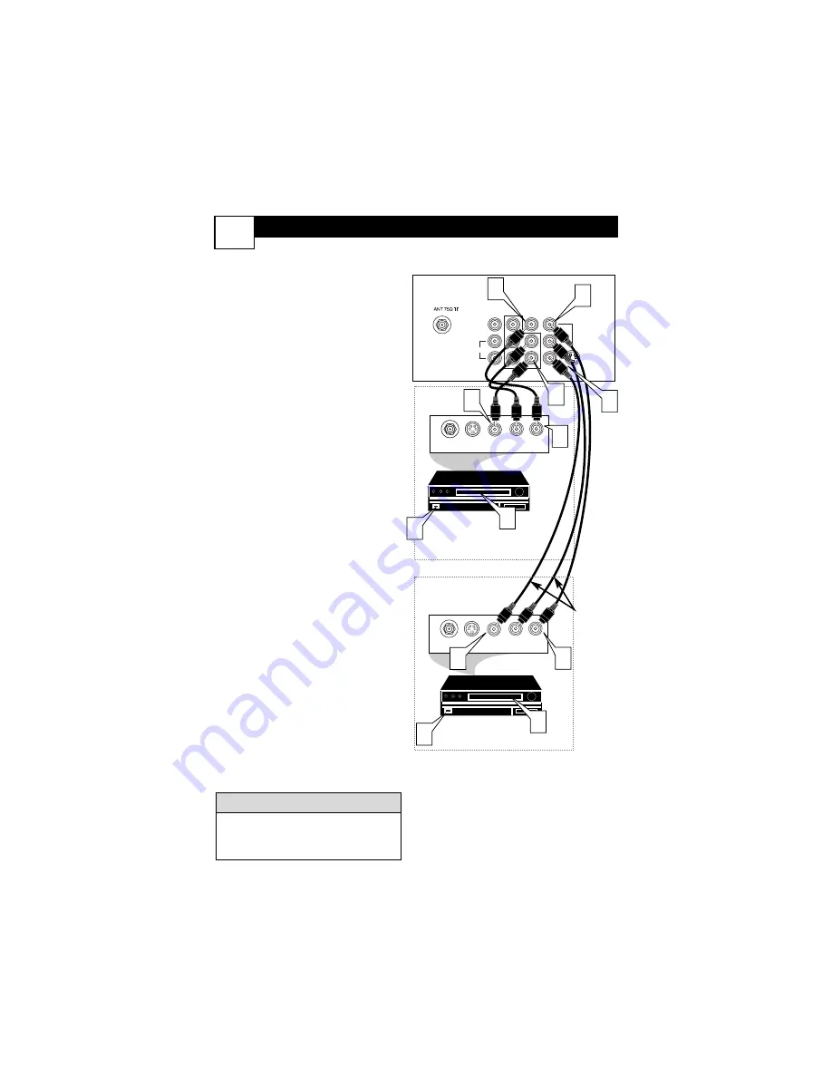
he TV’s audio/video input jacks
are for direct picture and sound
connections between the TV and a
VCR (or similar device) that has
audio/video output jacks. Both the
AV
1
and AV2 Input Jack connections
are shown on this page, but either
one can be connected alone. Follow
the easy steps below to connect your
accessory device to the AV
1
and AV2
IN Jacks located on the back of the
TV.
1
Connect the VIDEO (yellow)
cable
to the VIDEO
AV
1
IN
(or
AV2 IN) jack on the back of the
TV.
2
Connect the AUDIO (red and
white) cables
to the AUDIO (left
and right)
AV
1
IN
(or AV2 in)
jacks on the rear of the TV.
3
Connect the VIDEO (yellow)
cable
to the VIDEO OUT jack on
the back of the VCR (either one
or two) or accessory device being
used.
4
Connect the AUDIO (red and
white) cables
to the AUDIO (left
and right) OUT jacks on the rear
of the VCR (either one or two) or
accessory device being used.
5
Turn the VCR (either one or
two) or accessory device and
the TV ON.
6
Press the AV button to set the
TV to its AV1or AV2 channel.
7
With either of the VCRs (or
accessory devices) ON and a pre-
recorded tape (CD, DVD, etc.)
inserted,
press the PLAY button
to view the tape on the television.
Summary of Contents for US-24ST2200/27B
Page 41: ...NOTES 37 ...


