background image

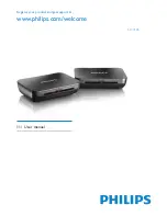
SLV3105

Register your product and get support at

www.philips.com/welcome

EN 

User manual

Summary of Contents for SLV3105

Page 1: ...SLV3105 Register your product and get support at www philips com welcome EN User manual ...

Page 2: ......

Page 3: ...etic and Electromagnetic Getting started 3 3 1 Connect transmitter 3 3 Enjoy 3 2 Connect receiver 3 4 Install the remote control blaster cord Remove interference on TV2 3 5 4 4 5 6 5 7 7 7 9 9 10 10 11 11 Technical data 4 12 5 Frequently asked questions 13 6 INDEX 16 1 Overview of the Wireless TV link Table of contents Table of contents 3 7 Declaration of Conformity 17 Engl i s h 3 EN ...

Page 4: ...ufacturer Concord Model Name CM 3AD09005 Power supply information for receiver and transmitter Input AC100 240V 120mA 50Hz 60Hz Output DC9V 500mA About operating and storage temperatures Operate in a place where temperature is always between 0 and o o 40 C 32 to 103 F Store in a place where temperature is o always between 10 and 70 C 14 to o 157 F Connect the power adapters only to a 100 240V AC 5...

Page 5: ...e human health and high environmental protection Your product is designed and manufactured with high quality materials and components which can be recycled and reused Do not dispose of your old product in your general household waste bin 1 4 Electric Magnetic and Electromagnetic Fields EMF 1 Philips Royal Electronics Manufactures and sells many consumer oriented products which usually as with any ...

Page 6: ...ct complies with the standards that are defined for it As the product is based on RF technology the quality of the image can be influenced by microwave ovens Bluetooth Wifi etc Therefore the product can suffer from the same kinds of interference as GSMs portable radios and other RF based products Important 6 EN ...

Page 7: ...ips com welcome 2 1 What s in the box Transmitter 1 Power light green on 2 On off switch 3 Power input connector DC 9V 4 Remote control blaster cord port 5 SCART cable 6 Wireless channel selection switch Find the CHANNEL switch on 4 available channels Control and display elements 6 5 4 3 2 1 2 2 Overview of the Wireless TV link Your Wireless TV link 7 Eng l is h 7 EN ...

Page 8: ...ht 7 Power light green on 8 On off switch 9 Power input connector DC 9V 10 SCART cable 11 Wireless channel selection switch Find the CHANNEL switch on 4 available channels Control and display elements 11 10 9 8 7 Receiver 12 13 8 Your Wireless TV link 8 EN ...

Page 9: ...a Switch on TV1 b Check that TV1 is working well c Switch on the connected video source d Check if TV1 shows the image of the video source The transmitter is connected correctly c The green LED on the front panel should be on Transmitter 5 Connect the remote control blaster cord D to the IR socket Please reference to 3 4 Install the remote control blaster cord to have more information 3 Connect th...

Page 10: ...ame number that on the transmitter A 1 Switch on TV2 2 Switch on the receiver B 3 Select the correct SCART input on TV2 4 Point the remote control of the video source to the receiver B 5 Operate the video source with its remote control 6 Check if TV2 shows the image of the video source The receiver is connected correctly 3 3 Enjoy All the operations listed on 3 1 and 3 2 should have been done Prep...

Page 11: ...the IR sensor on the front panel Note See the user manual of the video source for the exact location of the IR sensor on the front panel 3 Find the CHANNEL switch on the receiver B 4 Set the CHANNEL switch to the same number as on the transmitter A 3 5 Remove interference on TV2 1 Find the CHANNEL switch on the transmitter A T 2 Set the CHANNEL switch to a different number on the transmitter A in ...

Page 12: ...r System RF TV LINK Weight 0 290kg Dimensions 120X182X40 2mm Playback frequency range 2400 2470MHz Channels 4 Audio S N ratio 45dB at 15m Video S N ratio 50dB at 15m Audio Output level 2V Video Output level 1 1V Video Frequency Response 50Hz 5 5MHz Audio frequency response 40Hz 15kHz Power Requirements 9V 500mA IR Extender Transmitter IR Frequency 433 92MHz RF Output Power 7 9dBm IR carrier Freque...

Page 13: ...for communication See Remove interference on TV2 on page 10 The receiver B is out of range of the transmitter A The number of walls and ceilings between the receiver B and transmitter A restricts the distance Interference in the image on TV2 Slightly change the position of the receiver B or the transmitter A Change the wireless channel that is used for communication See Remove interference on TV2 ...

Page 14: ... with S VHS VCR Separate Video Home System Video Cassette Recorder Check if the SCART connector of the S VHS VCR gives signal in CVBS Composite Video Broadcast Signal See its user manual 14 Frequently asked questions 14 EN ...

Page 15: ...k Gives a VCR or DVD recorder the possibility to automatically take over the preset programming of the TV RF technology Technology based on radio frequency used for wireless connections SCART Single connector to easily connect audio and video equipment 15 En gl i s h 15 EN ...

Page 16: ...nnel 11 E Enjoy 10 F Frequently asked questions 13 G Getting started 9 I Interference 11 O Overview of the Wireless TV link 7 T Technical data 12 W What s in the box 7 Y Your Wireless TV link 7 R Remote control blaster cord 11 6 INDEX INDEX 16 16 EN ...

Page 17: ...re numéro et date de parution de la norme EN62311 2008 _ EN 301489 1 V1 8 1 2008 EN 301489 3 V1 4 1 2002 EN 300 220 1 V2 2 1 2008 _ EN 300 200 2 V2 2 1 2008 EN 300 440 1 V1 4 1 2008 EN 300 440 2 V1 2 1 2008 EN 60950 1 2006 A11 2009 Following the provisions of Conformément aux exigences essentielles et autres dispositions pertinentes de 1999 5 EC R TTE Directive Directive R TTE 1999 5 CE 2009 125 E...

Page 18: ...nklijke Philips Electronics N V All rights reserved Reproduction in whole or in part is prohibited without the written consent of the copyright owner Document number SLV3110_12_EN_UM_V1 2 145 131100112 master EN SLV3105_12_EN_UM_V1 0 ...

Reviews: