


1998 Feb 16
9
Philips Semiconductors
Product specification
CMOS digital decoding IC with RAM for
Compact Disc
SAA7345
R
EADING
Q-
CHANNEL SUBCODE FROM
SAA7345
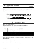
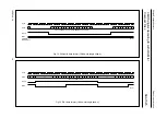
To read Q-channel subcode from SAA7345, the SUBQREADY-I signal should be selected as status signal. The subcode
read timing is shown in Fig.8.
Read subcode operation sequence
•
Monitor SUBQREADY-I status signal.
•
When this signal is LOW, and up to 2.3 ms after its LOW-to-HIGH transition, it is permitted to read subcode.
•
Set CL LOW, SAA7345 will output first subcode bit (Q1).
•
After subcode read starts, the microcontroller may take as long as it wants to terminate read operation.
•
SAA7345 will output consecutive subcode bits after each HIGH-to-LOW transition of CL.
•
When enough subcode has been read (1 to 96 bits), stop reading by pulling RAB LOW.
P
EAK DETECTOR OUTPUT
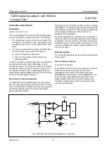
In place of the CRC-bits (bits 81 to 96), the peak detector information is added to the Q-channel data. The peak
information corresponds to the highest audio level (absolute value) and is measured on positive peaks. Only the most
significant 8 bits of the peak level are given, in unsigned notation. Bits 81 to 88 contain the LEFT peak value
(bit 88 = MSB) and bits 89 to 96 contain the RIGHT channel (bit 96 = MSB). Value is reset after reading Q-channel data.
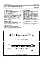
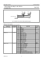
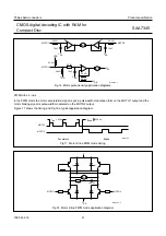
Fig.7 SAA7345 status READ timing.
DA (SAA7345)
MGA381 - 1
STATUS
CL
(microcontroller)
RAB
(microcontroller)
DA
(microcontroller)
high impedance
Fig.8 SAA7345 Q-channel subcode READ timing.
Q1
Q2
Q3
Qn–1
DA (SAA7345)
MGA382 - 1
Qn–2
Qn
STATUS
CRC
OK
CL
(microcontroller)
RAB
(microcontroller)


