Philips SA 230 Service Manual Download Page 5

1 - 4

Memory

(MUSIC & VOICE only)

Memory size 

The number of music and voice files depend on the available memory and size of f

With short file names more files will be supported.

This device has a built-in 64MB (Unit) memory space. Full memory capacity m
not be available as some memory will be reserved for the device. Use a MMC
SD external memory card (

Card

) to expand the memory size. 

By default, RUSH plays on a continuous mode: 

Both mem

internal follow

by external memory.

Using and formatting new cards for RUSH

1

Insert your card in the SA220 

CARD INSERT

slot.

2

Connect SA220 to your PC using the supplied USB cable.

3

Click

Start

y

Program

y

Philips RUSH Audio Player 

y

Format.

4

Choose the correct drive and click 

Start

.

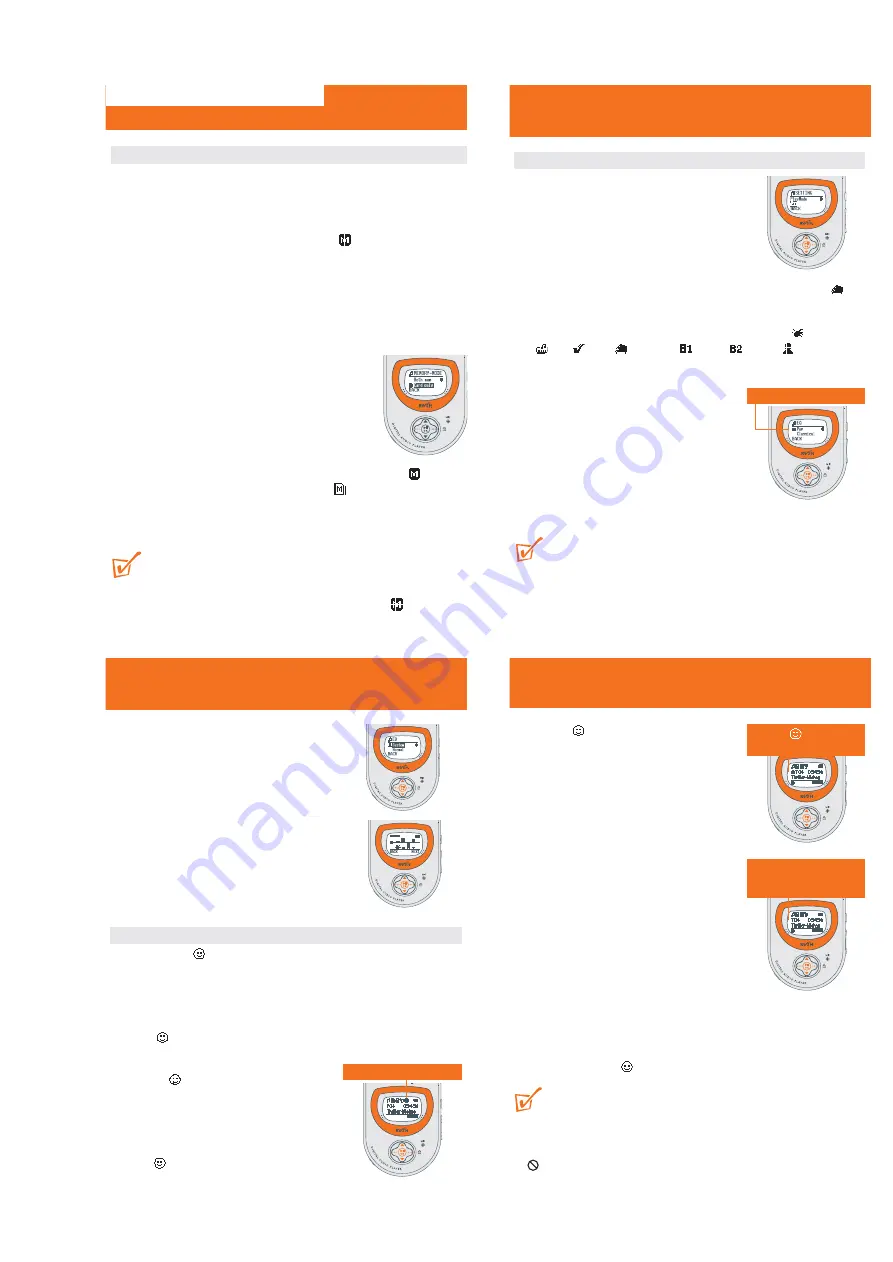
Selecting memory options 

1

To select the 

Memory

menu, use the ••• (right-

hand side, 

MENU

soft key), 

3

/

4

and

2;

OK

controls to select 

Info

or

Mode

.

To view the free memory capacity details (

Int Free

= internal memory and 

Ext Free

external memory,)

select

Info

.

To select memory playback mode, select either

Mode

y

Both mem

(to operate on in memory card 

) or 

Card o

(to operate on memory card only indicated by

).

2

Press ••• (left-hand side, 

BACK

soft key) once or more to exit the menu

display. Or allow several seconds for time out to return to the previous playba
display.

TIP:

– No music or voice playback is possible and the display shows 

No Files! 

if no c

is available and you have selected 

Card only

. Please select 

Both mem

fro

the

Memory

menu again to enable the device for playback.

– The 

Musicmatch

software will automatically create separate drives for the

respective internal and external memory.

INSTRUTION FOR USE

Equalizer

(MUSIC & VOICE only)

Equalizer sound options

1

During playback, press ••• (right-hand side,

MENU

soft key).

y

Display: shows 

SETTING

menu and the

submenu options.

2

Press

3

/

4

to scroll to 

EQ

.

3

Press

2;

OK

to confirm and enter the 

EQ

menu.

y

Display: shows the current sound icon and setting highlighted. E.g. 

Classical

4

Use

3

/

4

to scroll through the 8 possible options. 


Normal,

Rock,

Pop, Jazz, Classical, Bass1, Bass 

2, Custom,


Normal..

.

5

Press

2;

OK

to select the desired sound option.

6

Press ••• (left-hand side, 

BACK

soft key) once or

more to exit the menu display. Or allow several
seconds for time out to return to the previous
playback display.

7

You can also create your own sound with the

Custom

option

(see next chapter).

TIP:

– An EQ icon is only shown if you have selected the option in the EQ menu during

playback.

– No icon is shown during playback at the top of the display if you have selected

Normal

.

Current/ selected setting

Custom, Favorite

(MUSIC mode only) 

Custom: adjustable, personal sound
options

If you have selected 

Custom

, the display shows a set of

4 frequency bars which can be adjusted to provide a
personal setting.

1

Use the ••• (right-hand side, 

NEXT

soft key) and

2;

OK

controls to scroll and select the frequency:

B (BASS), M (MID), H (HIGH)

or

T (TREBLE)

.

2

Use the 

3

/

4

controls to adjust the sound level. 

3

Press

2;

OK

to confirm.

4

Use

3

/

to scroll through and find the track for

deletion.

Favorite

The

Favorite

menu 

option allows you to create up to 10 favorite track/file entries

in the device memory for music playback. You can add tracks, numbered from 

01-10,

to

Favorite

at different times. You can also switch to normal playback (

Off

) or switch

off the device, without deleting the list.

Use the ••• (right-hand side), 

3

/

4

and

2;

OK

controls to scroll and select

MENU

y

SETTING

y

Favorite

.

y

shows 3 submenus 

On/ Off

,

View list 

and

Remove list

.

Check out the submenu options as follows:

Selecting On

This activates playback of the tracks already saved
under the 

Favorite

list only.

Use the •••(right-hand side), 

3

/

4

and

2;

OK

controls to scroll and select 

Favorite

y

On/Off

y

On

.

appears in top right hand side of the

display, and your track numbers are indicated
by

Fxx (Favorite)

instead of 

Txx

(

Favorite

mode switched off).

Favorite List 

activated

Favorite

(MUSIC mode only) 

Selecting Off 

and 

saving 

tracks 

In the 

Favorite Off

mode, you can save and add further

favorite tracks.

1

During playback, use the ••• (right-hand side,

MENU

soft key), 

3

/

4

and

2;

OK

controls to

scroll and select 

Favorite

y

On/Off

y

Off

.

2

Press ••• (left-hand side) if you want to add the
current track into the 

Favorite

(program) list.

Selecting ‘View list’ 

This allows you to view your programmed tracks status.

Use the ••• (right-hand side), 

3

/

4

and

2;

OK

controls to scroll and select 

MENU

y

SETTING

y

Favorite

y

View list

.

Details of programmed tracks appear. Use

3

/

4

to scroll through the list.

No files!

appears if no tracks were

previously saved as a favorite.

‘Remove list’: How to erase FAVORITE 

In the 

Favorite Off

mode,

Remove list

allows you to erase your programmed track

list completely.

1

Use

3

/

to scroll through and find the track for deletion.

2

Press

2;

OK

to confirm erasing.

y

Display shows: 

LIST REMOVED!

TIP:

Favorite

programmed entries cannot be erased by removing the battery from the

device.

No files!

appears if no tracks were previously saved as a 

Favorite

.

appears if you attempt to select 

Remove list 

in

Favorite On 

mode.

Favorite

switched on:

track saved as a 

Favorite

Favorite

switched off:

track not saved as a

Favorite

Summary of Contents for SA 230

Page 1: ...side view 4 4 Layout diagram component side view 4 4 Exploded view 5 1 Mechanical partslist 5 1 Electrical partslist 6 1 6 2 3140 785 32200 Published by LX 0325 Service Audio Printed in The Netherlands Subject to modification Digital Audio Player TABLE OF CONTENTS Copyright 2001 Philips Consumer Electronics B V Eindhoven The Netherlands All rights reserved No part of this publication may be reprod...

Page 2: ...S N stereo 51 5dBf 3dB limiting point 23 5dBf S N ratio A weighted mone 45dBA S N ratio A weighted stereo 45dBA Channel separation 0 4 1 5KHz input 68dBf 18 20 15dB Channel unbalance 3dB Overall distortion 7 Image rejection ratio 20dB Frequency response 3dB Current consum0ption Battery lifetime Neck strap Armband If you would like help or more information on your RUSH product visit the Philips web...

Page 3: ...l and serial numbers are located inside the battery compartment Switching Off Press and hold 2 OK until the power down status bar is complete y Display shows Continue Holding To Power Off and the status bar before switching off TIP If you have trouble switching off first make sure the button lock feature is deactivated the device is in playback mode and NOT in any MENU option display Switching ON ...

Page 4: ...ivity by securing it to the supplied armband 1 Fit the device into the rubber buckle A with the headphone jack aligned to the jack hole 2 Position the armband round your arm Thread the strap B and fasten up for a snug fit Neck Strap 1 Thread the neck strap A through the ring B 2 Buckle up C play pause search MUSIC VOICE only Playing and Pausing Music Voice Files 1 During playback use the MODE butt...

Page 5: ...uring playback at the top of the display if you have selected Normal Current selected setting Custom Favorite MUSIC mode only Custom adjustable personal sound options If you have selected Custom the display shows a set of 4 frequency bars which can be adjusted to provide a personal setting 1 Use the right hand side NEXT soft key and 2 OK controls to scroll and select the frequency B BASS M MID H H...

Page 6: ...d important discussions Maximum Voice recording time approximately 4 hours if using all the built in memory on Low sound quality recording setting Preparation for VOICE recording quality 1 In the VOICE mode use the and 2 OK controls to scroll and select MENU y SETTING y QUALITY 2 In the QUALITY menu use the 3 4 and 2 OK controls to scroll and select the desired quality High Medium or Low 32K 16K o...

Page 7: ...0 from computer when the recovering is in progress 8 Once the recovery process is complete click on the Unplug or Eject Hardware removal icon on your PC task tray When you reach the message The USB Mass Storage device can now be safely removed from the system click OK For Windows98 users there is no removal icon Instead please check your SA220 shows the READY display before you unplug SA220 9 Unpl...

Page 8: ... that parts which are identical with those specified be used Safety components are marked by the symbol i Le norme di sicurezza estigono che l apparecchio venga rimesso nelle condizioni originali e che siano utilizzati i pezzi di ricambiago identici a quelli specificati Componenty di sicurezza sono marcati con ñ Veiligheidsbepalingen vereisen dat het apparaat in zijn oorspronkeliijke toestand word...

Page 9: ...ss to the componentside of the printed board assembly proceed as follows 1 Remove battery door assy 2 Destroy plastic shell like following diagram 3 Remove plastic shell 4 Remove screws 4pcs 2 pcs in battery compartment 5 Remove bottom cabinet DISMANTLING THE SET To dismantle the Set proceed as follows 1 Remove batter door assy 2 Destroy plastic shell like following diagram 3 Remove plastic shell ...

Page 10: ...nections 1MΩ 4822 320 11307 Extendible cable 2m 2MΩ to connect wristband to connection box 4822 320 11305 Connecting cable 3m 2MΩ to connect table mat to connection box 4822 320 11306 Earth cable 1MΩ to connect any product to mat or to connection box 4822 320 11308 KIT ESD3 combining all 6 prior products small table mat 4822 310 10671 Wristband tester 4822 344 13999 HANDLING CHIP COMPONENTS ...

Page 11: ...D2 POWER P Digital Core Ground 2 11 11 H7 VddD2 POWER P Digital Core Power 2 12 12 M5 CF_A0 EMC CF O CompactFlash Address 0 GP32 GPIO I O GP1B8 RAM_A0 SDRAM O SDRAM Address 0 NA 13 K5 CF_A22 EMC CF O CompactFlash Address 22 GP69 GPIO I O GP2B21 RAM_A22 SDRAM O SDRAM Address 22 13 14 L5 CF_A1 EMC CF O CompactFlash Address 1 GP33 GPIO I O GP1B9 RAM_A1 SDRAM O SDRAM Address 1 NA 15 M6 CF_A21 EMC CF O...

Page 12: ...lash Address 15 GP62 GPIO I O GP2B14 RAM_A15 SDRAM O SDRAM Address 15 20 30 L9 CF_A8 EMC CF O CompactFlash Address 8 SM_CLE EMC SM O SmartMedia NAND Command Latch Enable GP40 GPIO I O GP1B16 RAM_A8 SDRAM O SDRAM Address 8 NA 31 K9 CF_A14 EMC CF O CompactFlash Address 14 GP61 GPIO I O GP2B13 RAM_A14 SDRAM O SDRAM Address 14 21 32 L10 CF_A9 EMC CF O CompactFlash Address 9 SM_ALE EMC SM O SmartMedia ...

Page 13: ... Data 13 33 50 H10 CF_D3 EMC CF I O CompactFlash Data 3 SM_D3 EMC SM I O SmartMedia NAND I O 3 GP27 GPIO I O GP1B3 RAM_D3 SDRAM I O SDRAM Data 3 NA 51 G11 CF_D12 EMC CF I O CompactFlash Data 12 GP76 GPIO I O GP3B4 RAM_D12 SDRAM I O SDRAM Data 12 34 52 G10 CF_D4 EMC CF I O CompactFlash Data 4 SM_D4 EMC SM I O SmartMedia NAND I O 4 GP28 GPIO I O GP1B4 RAM_D4 SDRAM I O SDRAM Data 4 NA 53 G12 CF_D11 E...

Page 14: ...TT POWER P Battery Input 57 86 B8 LINE1L CODEC A Line in 1 Left 58 87 A8 LRADC SYSTEM A Low Resolution ADC Input 59 88 C8 LINE1R CODEC A Line in 1 Right 60 89 C7 VssA2 POWER P Analog Ground 2 61 90 B7 VddA2 POWER P Analog Power 2 62 91 B6 HPL CODEC A Headphone Line out Left 63 92 C6 VssHP POWER P Headphone Ground NA 93 D6 DCDC_mod1 DCDC P DCDC mode pin 1 64 94 D5 VddHP POWER P Headphone Power 65 9...

Page 15: ...RASn SDRAM O SDRAM RASn 93 131 H4 GP2 GPIO I O GP0B2 I2S_DataI2 I2 S I I2 S Data In 2 NA 132 J3 GP86 GPIO I O GP3B14 RAM_CASn SDRAM O SDRAM CASn 94 133 H2 GP1 GPIO I O GP0B1 I2S_DataI1 I2S I I2S Data In 1 NA 134 H1 GP87 GPIO I O GP3B15 RAM_WEn SDRAM O SDRAM WEn 95 135 J1 GP0 GPIO I O GP0B0 I2S_DataI0 I2 S I I2 S Data In 0 NA 136 J2 GP92 GPIO I O GP3B20 I2S_DataI0 I2S I I2S Data In 0 Alternate pin ...

Page 16: ...1 RESAMP LIMITER LEVEL DEMOD GAIN STABI IF COUNT POWER SUPPLY MPX DECODER SDS I2C 3Wire VCO TUNING SYSTEM Pilot Iref IF Center Freq Adjust ADC TEA5767HN AGC SWPORT 30 31 17 BUS MUX Prog div out Ref div out 22u Vcc 22n 22Ω Vdd 22Ω 15 XTAL OSC 14 Mono 13 12 11 Bus Enable SOFT MUTE 24 56p 10p 100n 2 2n 47n 22n 33kΩ Ccomp 10kΩ Cpull 22n Ccomp and Cpull data depend on Xtal spec 33n Vccosc 22n D1 D2 L3 ...

Page 17: ...put2 crystal oscillator PHASEDET 18 phase detector loop filter PILDET 19 pilot detector lowpass filter switch for test mode NC3 20 not connected NC4 21 not connected VAFL 22 Left audio output VAFR 23 Right audio output TMUTE 24 time constant for soft mute MPXOUT 25 FM demodulator MPX output VREF 26 Reference vottage TIFCENTER 27 time constant for IF center adjust LIMDEC1 28 decoupling IF limiter1 ...

Page 18: ...dphone Jack Head Phone HOLD VOL VOL REW FF EQ Bookmark HOLD MENU 3 Color LED Back Light USB_Sense VDD_2V5 DCDC_Vbg Vbus_5V XTAL VDD_D VDD_IO USB D_ USB D USB_SELECT 1 5V BATT AAA USB Connector L R Pswitch Power Play Pause 6 poles PW_On VDD_3V3 SD CARD FM Module Elite MIC BLOCKDIAGRAM ...

Page 19: ...1 8 8 6 0 B C I RST D Power Play Pause either a 30mil trace or as part CAP3 E G F J H 17 18 19 20 A MIC E FOR 3410 M J K Route DC DC_GND back to L K L M 47K 3223 7218 SI2312DS 2450 1n5 HP_GND 1 2 3 4 5 6 7 8 1405 SKRHABE TP20 2468 10n 3452 22K TP21 2407 1u TP22 100u 2408 100n 22p 2409 5227 2469 3221 1K0 100K 3445 4200 2446 1u0 AGND 5209 3236 47K TP17 2421 100n 47K 3444 100n 2430 7213 SI2312DS 3405...

Page 20: ...4 2 4 2 MAIN BOARD LAYOUT DIAGRAM ...

Page 21: ...03 0u033 5107 5106 120n 2126 22n TMUTE 24 VAFL 22 VAFR 23 VCC 34 VCCVCO 5 VCOTANK1 3 VCOTANK2 4 VDIG 7 VREF 26 WRIE READ 11 XTAL1 16 XTAL2 17 10 NC3 20 NC4 21 NC5 30 NC6 31 NC7 40 PHASEDET 18 PILDET 19 RFGND 36 RFIN1 35 RFIN2 37 SWPORT1 14 SWPORT2 15 TIFCENTER 27 AGND 33 BUSENABLE 13 BUSMODE 12 CAGC 38 CLOCK 9 CPOUT 2 DATA 8 DGND 6 IGAIN 32 LIMDEC1 28 LIMDEC2 29 LOOPSW 39 MPXOUT 25 NC1 1 NC2 F019 ...

Page 22: ...4 4 4 4 TUNER BOARD LAYOUT DIAGRAM ...

Page 23: ...1 RUSH3 USB PLUG 406 3140 114 61571 USB PLUG SA230 407 3140 114 45321 RUSH3 BUTTON SET 408 3140 111 22272 RUSH3 POS PLATE 409 3140 111 01332 RUSH3 SPRING NEG 411 3140 114 45331 RUSH3 BOTTOM CABINET 411 3140 114 61551 BOTTOM CABINET SA230 412 3140 117 63621 BATTERY DOOR ASSY 412 3140 117 69041 BATTERY DOOR ASSY SA230 413 3140 110 41381 SCR 1 4X2 5 PH PH BKZP TP SA230 413 3103 300 41570 SCREW P 1 4X...

Page 24: ...35 71040 100nF Y5V 16V 3412 4822 117 11297 100K 1 16W 2423 2020 552 96618 1nF 10 X7R 50V 3413 4822 117 11297 100K 1 16W 2424 2020 552 96618 1nF 10 X7R 50V 3414 4822 117 13545 100R 5 2430 3198 035 71040 100nF Y5V 16V 3415 4822 117 13545 100R 5 2431 3198 035 71040 100nF Y5V 16V 3419 4822 117 13606 10K 5 0 0062W 2432 4822 126 14519 22pF 5 50V NP0 3422 4822 117 13606 10K 5 0 0062W 2433 4822 126 14519 ...

Page 25: ...D SM 2 2µH 20 2120 2238 787 19843 33nF 80 20 Y5V 16V 5103 2422 536 00358 IND FXD SM 2 2µH 20 2121 3198 017 41050 1µF Y5V 10V 5104 2422 536 00358 IND FXD SM 2 2µH 20 2122 3198 017 41050 1µF Y5V 10V 5106 2422 536 00549 IND FXD SM 0 12µH 2 2125 2020 552 96623 2 2nF 10 X7R 50V 5107 2422 536 00469 IND FXD SM 33N 2 2126 2020 552 96632 22nF 10 X7R 16V 5108 2422 536 00469 IND FXD SM 33N 2 2127 2020 552 96...

Reviews: