Mechanical Instructions
EN 14
SDI PDP 2K7
4.
4.1.4
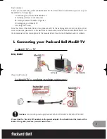
Exchange of LBE and LBF board - 42” HD W2
1.
Remove the screws in order of 2-3-1-4 from the heatsink
and remove the heatsink (“Photos 1 & 3”).
2.
Remove the TPC, FFC, and power cable from the
connectors.
3.
Remove all the screws from the defective board.
4.
Remove the defective board.
5.
Place the new board and then screw tightly.
6.
Clean the connectors.
7.
Re-connect the TCP, FFC, and power cable to the
connectors.
8.
Re-assemble the TCP heat sink. Use the screw mounting
order 2-3-1-4.
Caution:
If you screw too tight, it is possible to damage the
Driver IC of the TCP.
Figure 4-9 Photo 1 - Heatsink 42” HD W2
Figure 4-10 Photo 2 - Exchange of LBE, LBF board 42” HD W2
Figure 4-11 Photo 3 - Heat sink removal
H_16870_027.eps
020407
H_16870_028.eps
020407
G_16
38
0_022.ep
s
160606