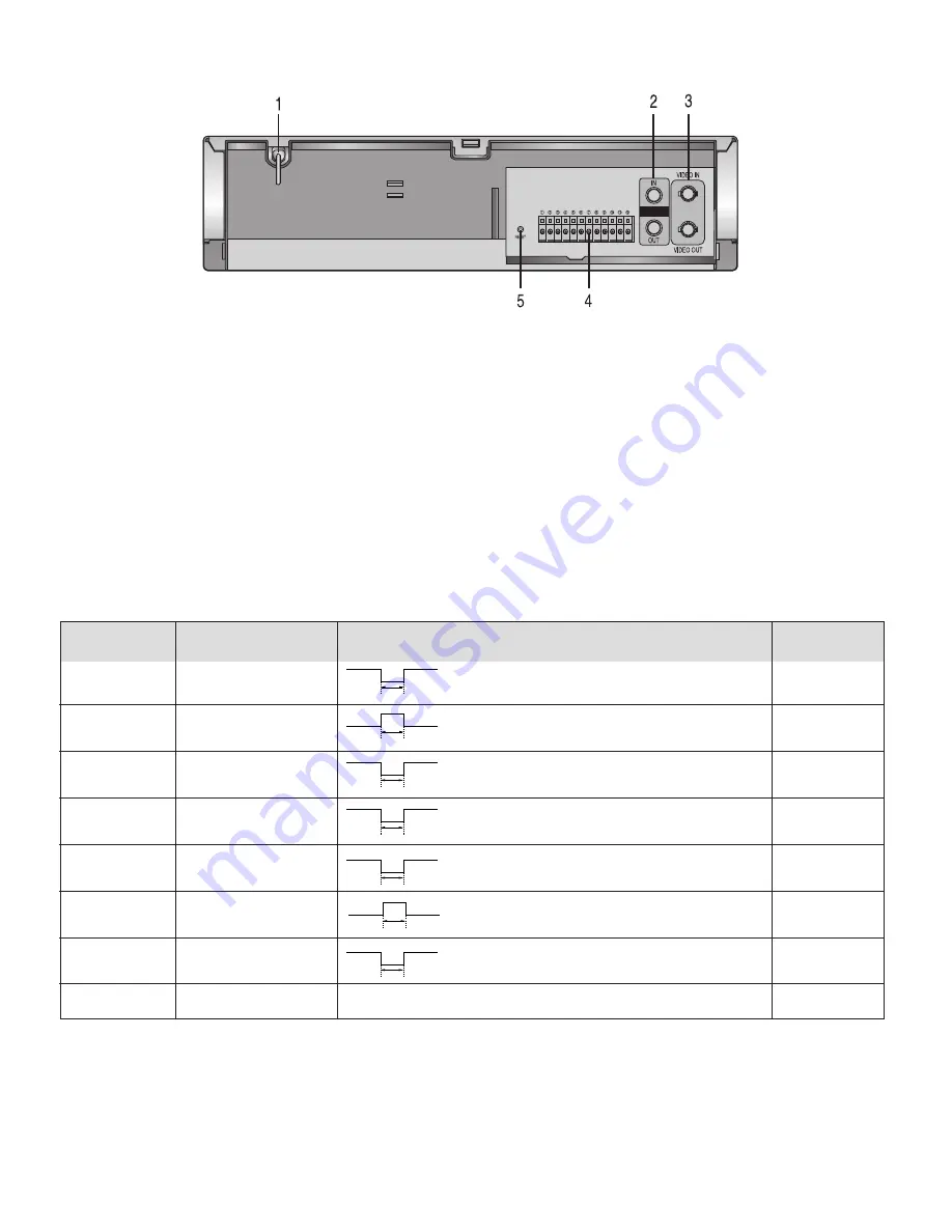
Rear Connection Panel
1. POWER CORD - Connect to correct power supply.
2. AUDIO IN/OUT - Accepts an audio signal from a
camera, external sound equipment or another recorder
(Line: –6 dBm, 47 kOhm, unbalanced). Provides an
audio output for a monitor or another VCR (–9 dBm,
1.5 kOhm, unbalanced).
3. VIDEO IN/OUT - IN - Receives video signal from a
video camera or another VCR. OUT - For connection to
monitor.
4. 12-PIN TERMINAL - Provides inputs/outputs for
operational use:
Pin 1 – Alarm IN
Pin 3- Alarm OUT
Pin 5 – Series IN
Pin 6 – Series OUT
Pin 8 – VEXT
Pin 10 – Tape end OUT
Pin 11 – 1-Shot record IN
Pins 2, 4, 7, 9, 12 - GND
5. RESET - Press to reset the VCR.
1-6
AUDIO
FIG. 3 - RT30A & RT960A REAR
TERMINAL
FUNCTION
SIGNAL LEVEL
IN/OUT
1.
ALARM IN
V
IH
: 4-5V V
IL
: 0--.6V, T : above 500 msec.
INPUT
3.
ALARM OUT
V
OH
: 4-5V V
OL
: 0--.6V, T : Alarm rec. state
OUTPUT
5.
SERIES IN
V
IH
: 4-5V V
IL
: 0--.6V, T : above 500 msec.
INPUT
6.
SERIES OUT
V
OH
: 4-5V V
OL
: 0--.6V, T : above 500 msec.
OUTPUT
8.
VEXT
V
OH
: 4-5V V
OL
: 0--.6V, T : above 500 msec.
OUTPUT
10.
TAPE END OUT
V
OH
: 4-5V V
OL
: 0--.6V, T : above 500 msec.
OUTPUT
end of tape or low tape or DECK error
11.
1-SHOT REC IN
V
IH
: 4-5V V
IL
: 0--.6V, T : above 500 msec.
INPUT
2, 4, 7, 9, 12.
GND
OV
COMMON
V
IH
V
IL
T
V
OH
V
OL
T
V
IH
V
IL
T
V
OH
V
OL
T
V
OH
V
OL
T
V
OH
V
OL
T
V
IH
V
IL
T
Summary of Contents for RT30A
Page 2: ......
Page 26: ...1 24 ...


