background image

 1

 2

 3

 4

 5

 6

 7

 8

 9

10

OUT1

OUT0

IN0

OUT2

IN1

IN2

IN3

IN4

GND

POW

-KEY

 1

 2

 3

 4

 5

 6

 7

 8

 9

10

 1 
 2 
 3 
 4 
 5 
 6 
 7 
 8 
 9 
10
11 
12
13
14
15
16
17
18
19
20
21
22
23
24

F-
F+
T+
T-
C
D
CD/DVDSW
RFO
A
B
F
GND
V20
+P5V
E
NC
VR/CD
VR/DVD
LD/DVD
MD
VCC
NC
LD/CD
GND

 1 
 2 
 3 
 4 
 5 
 6 

 1 
 2 
 3 
 4 
 5 
 6 

LIMIT
GND
SL+
SL-
SP+
SP-

 1
 2
 3
 4
 5
 6
 7
 8
 9
10
11
12
13
14
15
16
17
18
19
20
21
22
23
24

 1
 2
 3
 4
 5
 6
 7
 8
 9
10
11
12
13
14
15
16
17
18
19
20
21
22
23
24

1
2
3
4

GND
BRIGHT-CON
TFTON
TFT5V

1
2
3
4

30
29
28
27
26
25
24
23
22
21
20
19
18
17
16
15
14
13
12
11 
10
 9 
 8 
 7 
 6 
 5 
 4 
 3 
 2
 1 

XS6

FUNCTION BUTTON PCB

LOADING

LCD

 POWER PCB

XS1

TFT3.3V
TFT3.3V
GND
TFT3.3V
SPS
CLS
MOD2
GND
GND
VGL
VGH_+16V
GND
GND
TFT5V
TFT5V
B
G
R
GND
NC
GND
TFT3.3V
GND
MOD1
CLD
NC
NC
SPIO
VEE_-14.5V
COM

VCC
VCC
VDD33
VDD33
NC
GND
SPL+
SPL-
SPR-
SPR+
GND
GND
PWM
NC
RESET
SCL
SDA
GND
CVBSIN
GND
C-OUT
Y-OUT
GND
GND

1

2

3

4

5

6

7

1

2

3

4

5

6

7

BA

TT+

BA

TT+

BA

TT+

THM

GND

GND

GND

BATTERY

1
 2 
 3 
 4 
 5 
 6 
 7 
 8 
 9 
10
11 
12
13
14
15
16
17
18
19
20
21
22
23
24

30
29
28
27
26
25
24
23
22
21
20
19
18
17
16
15
14
13
12
11
10
 9
 8
 7
 6
 5
 4
 3
 2 
 1

I2

JX1

XS5

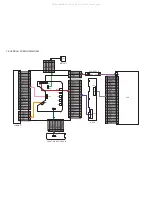
7.0 OVERALL WIRING DIAGRAM 

XS8

XS3

JS5

XS2

XS1

JS002

JS2

JS1

JS6

JS3

XS2

 2 
 1

XS4

 IF PCB

All manuals and user guides at all-guides.com

Summary of Contents for PET708

Page 1: ... 7 Electrical Diagram 8 Component Layout 9 Service Part List 10 Revision List 11 Copyright 2005 Philips Consumer Electronics B V Eindhoven The Netherlands All rights reserved No part of this publication may by reproduced stored in a retrieval system or transmitted in any form or by any means electronics mechanical photocopying or otherwise without the prior permission of Philips Service Manual All...

Page 2: ...annel Balance 1dB Supported disc type DVD video discs Audio CD MP3 CD In addition this unit can play DVD R DVD RW and CD R CD RW that contains audio titles or MP3 or JPEG files You cannot play disc other than the above listed CVD CD ROM CD Extra CD G and CD I discs cannot be played on this DVD player Software upgrades For the best performance of your DVD Portable Check www philips com support for ...

Page 3: ...ne della più grande cauzione alla loro manipolazione Durante le riparazioni occorre quindi essere collegato allo stesso potenziale che quello della massa dell apparecchio tramite un braccialetto a resistenza Assicurarsi che i componenti e anche gli utensili con quali si lavora siano anche a questo potenziale Pour votre sécurité ces documents doivent être utilisés par des spécia listes agréés seuls...

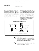
Page 4: ...r replacement if it was subject to electrostatic discharge during replacement its life might be shortened When replacing use a conductive mat soldering iron with ground wire etc to protect the laser diode form damage by static electricity And also the LSI and IC are same as above Soldering iron with ground wire or ceramic type Ground conductive wrist strap for body Conductive mat The ground resist...

Page 5: ... located and corrected Repeat the above test with the DVD VIDEO PLAYER power plug reversed NEVER RETURN A DVD VIDEO PLAYER TO THE CUSTOMER WITHOUT TAKING NECESSARY CORRECTIVE ACTION READING SHOULD NOT EXCEED 0 3V DVD VIDEO PLAYER AC OUTLET AC VOLTMETER Test all exposed metal Voltmeter Hook up for Leakage Current Check 0 15uF 150V AC 1500 10W 5000 per volt or more sensitivity Good earth ground such...

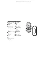
Page 6: ... once to stop playback and store the stop position Press twice to stop playback completely 9 9 Starts pause resumes playback VOL Volume control Headphones jack 11 AV OUT Audio video output jack DVD PLAYER LAYOUT PHONES AV IN Audio video input jack MENU Displays MENU page SETUP Enters SETUP menu 4 Search backward or search forward OPEN Opens disc door to insert or remove disc 5 DC IN 12V Power supp...

Page 7: ...D camera angle SUBTITLE Subtitle language selector LANGUAGE Language selector MENU Displays MENU page SETUP Enters SETUP menu Remote Control 3 4 Up down left right cursor Confirms selection On Screen Display on off INFRA RED PORT BATTERY COMPARTMENT 10 11 12 13 14 Pause playback Press twice to stop playback For previous or next chapters tracks or titles 9 9 Search backward or search forward 7 8 7 ...

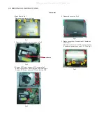
Page 8: ...ery PCB board as Fig 3 Broken connection of DVD driver and every PCB board Remove DVD driver and main PCB and function PCB Fig 3 4 Fig 4 5 Remove top cover as Fig 5 Fig 5 Broken connection of speaker and IF board and power board Remove screws to remove TFT board shield and IF board and power board and LCD TFT as Fig 5 soldered All manuals and user guides at all guides com ...

Page 9: ...for Europe 5 Press key to input preference region code see below table 6 Switch off and re switch on the product Verify Region code change done 7 Region Code Region 1 USA 2 EUROPE 3 ASIA PACIFIC 4 AUSTRALIA NEW ZEALAND LATAM 5 RUSSIA INDIA 6 CHINA REMARKS 1 Password is CONFIDENTIAL 2 Region code is printed on product type plate Due to DVD legislation region codes different to assigned region may n...

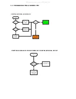
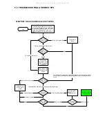
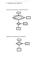
Page 10: ...tart set OK Check if the power and play button OK replace connector and switch unit replace MAIN BOARD go to other SYMPTOM no yes yes no replace DVD drive SYMPTOM NO IMAGE OR SOUND COMES OUT FROM THE EXTERNAL OUTPUT start Check operation of the DVD drive Does the DVD drive work yes no Replace the main board or the connector All manuals and user guides at all guides com ...

Page 11: ...en harness yes Remove the LCD cover and plate of the LCD unit to check the connector of the FL harness Is the connector OK no Repair connector Replace FL inverter or LCD no yes Is the connector broken Replace LCD harness or main board yes Remove the LCD cover and plate of the LCD unit to check the connection of the harness to the LCD unit no Is the connection OK Connect the LCD harness to the LCD ...

Page 12: ...DVD drive and main board Not OK Pick up lens light up OK Insert a DVD disc and turn on the power What is the reaction of the DVD drive The DVD drive works but the initializing operation of the optical pick up lens does not start the optical pick up lens operates twice or abnormal noise sound Replace DVD drive or main board DVD drive does not work The operation of the DVD player stops at initializi...

Page 13: ... the LED lights up orange while the AC adapter is connected and does the DVD drive operate OK NOTE For this check use a battery which is not fully charged because the LED does not light when the battery is fully charged Before this check make sure other function work correctly no SYMPTOM NO SOUND COMES FROM THE HEADPHONES start Replace main board yes Insert a good headphones and check if the probl...

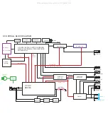
Page 14: ...hanism DRIVER SA5954 8M FlashROM KH29LV800CBTC 70G 64M SDRAM HY57V641620ETP 7 C TC4W53 27MHz AUDIO D A PCM1754 MX88V462UCG TFT MONITOR AUDIO AMP UTC4558 TPA6011 74HCU04 27MHz VIDEO OUT AUDIO OUT PHONE OUT SPEAKER LOUT SPEAKER ROUT L R L R DRIVER 5V 5V AUDIO 5V 5V 3 3V 1 8V AUDIO 5V TFT POWER 3 3V 5V 2 5V 16V 13V COAXIAL OUT VIDEO IN AUDIO IN All manuals and user guides at all guides com ...

Page 15: ... 16 15 14 13 12 11 10 9 8 7 6 5 4 3 2 1 XS6 FUNCTION BUTTON PCB LOADING LCD POWER PCB XS1 TFT3 3V TFT3 3V GND TFT3 3V SPS CLS MOD2 GND GND VGL VGH_ 16V GND GND TFT5V TFT5V B G R GND NC GND TFT3 3V GND MOD1 CLD NC NC SPIO VEE_ 14 5V COM VCC VCC VDD33 VDD33 NC GND SPL SPL SPR SPR GND GND PWM NC RESET SCL SDA GND CVBSIN GND C OUT Y OUT GND GND 1 2 3 4 5 6 7 1 2 3 4 5 6 7 BATT BATT BATT THM GND GND GN...

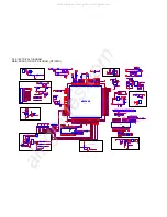
Page 16: ...ACVSSB 177 CVBS 175 FS 173 DACVSSC 174 ASDATA0 164 DACVDDC 171 SPDIF 170 MC_DATA 169 DVDD3 168 VREF 172 ASDATA3 167 ASDATA2 166 ASDATA1 165 ALRCK 163 XTALO 193 VSY 44 IOA2 47 DVDD18 48 IOA3 49 IOA4 50 IOA5 51 AD3 78 AD4 79 DACVDDB 176 APLLVDD3 183 VCM 188 AL 189 AR 187 MT1389D N4 MT1389D 1389D MT1389D N4 MT1389D 1389D 1 2 3 VD1 STZ6 2N VD1 STZ6 2N R53 1K R53 1K 4 4 5 5 1 1 2 2 3 3 VD8 TC7S08 VD8 T...

Page 17: ...C55 100N C55 100N 1 2 3 4 5 6 JS3 HSJ1494 01 010 JS3 HSJ1494 01 010 1 2 3 VD21 STZ6 2N VD21 STZ6 2N L14 0 L14 0 R61 4R7 R61 4R7 R84 10K R84 10K R81 1K R81 1K R106 100K R106 100K R83 6K8 R83 6K8 C65 2 2U C65 2 2U R89 10 R89 10 VD12 ISS355 VD12 ISS355 R60 4K7 R60 4K7 R56 33 R56 33 C62 22U 16V C62 22U 16V R59 10K R59 10K C51 100N C51 100N R28 10K R28 10K R109 10K R109 10K R63 1K R63 1K C72 100U 16V C...

Page 18: ...28 BIAS 27 VINTK 26 CTKERR1 OP1IN 25 CTKERR2 OP1IN 24 VINLD 23 PREGND 22 PVCC2 21 VNFTK OP1OUT 20 PGND VCC2 19 VOLD 18 VOLD 17 VOTK 16 VOTK 15 GND 29 GND1 30 N12 BA5888FP N12 BA5888FP C73 100P C73 100P R130 20K R130 20K C91 150PF Implementation C91 150PF Implementation C15 10U 10V C15 10U 10V C81 10N C81 10N R20 0 R20 0 C82 10U 16V C82 10U 16V R136 0R5 R136 0R5 C88 2N2 C88 2N2 R129 20K R129 20K C1...

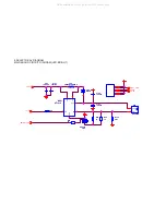
Page 19: ...240A VD6 B240A R30 1K R30 1K R36 15 R36 15 VCC 1 FB 2 XS4 HS0038B XS4 HS0038B R172 4R7 R172 4R7 1 2 3 4 5 6 LX 1 GND 2 VIN 6 OVP 5 FB 3 EN 4 N001 AT1313 N001 AT1313 R95 15 R95 15 R33 33 R33 33 L22 CDRH6D38 4R7MC L22 CDRH6D38 4R7MC C103 10U 16V C103 10U 16V 8 0 ELECTRICAL DIAGRAM MAIN BOARD CIRCUIT DIAGRAM LED BRIGHT All manuals and user guides at all guides com ...

Page 20: ...2 C6 47U 16V C6 47U 16V C220 10K C220 10K R230 0 R230 0 L12 601H L12 601H CB11 100N CB11 100N C228 100N C228 100N 1 8 2 7 3 6 4 5 RN2 22 4 RN2 22 4 C194 100N C194 100N C22 10U 10V C22 10U 10V CB12 100N CB12 100N R1 500K R1 500K CB29 1UF CB29 1UF CB3 100N CB3 100N CB2 100N CB2 100N 1 2 3 4 5 6 7 8 9 10 11 12 13 14 15 16 17 18 19 20 21 22 23 24 25 26 27 28 29 30 31 32 33 34 XS1 30PIN XS1 30PIN C146 ...

Page 21: ...P C179 10U 10V C179 10U 10V C201 10U 16V C201 10U 16V C198 100N C198 100N R189 68K R189 68K VD03 a1587 VD03 a1587 CB19 100N CB19 100N C207 10U 16V C207 10U 16V C54 100N C54 100N IN 1 GND 3 OUT 2 N19 BA05 N19 BA05 R188 18K R188 18K C169 100N C169 100N C212 10u 10v C212 10u 10v CB58 100N CB58 100N C202 100N C202 100N IN 1 GND 3 OUT 2 N17 BA05 N17 BA05 1 2 3 4 5 6 XS3 BAT XS3 BAT R202 75 R202 75 S2 1...

Page 22: ...2 HEC4801 010010 JS2 R01 10 R01 10 F1 0430003WR F1 0430003WR 2 1 C2 1UF C2 1UF C02 100N C02 100N L001 33uH L001 33uH C50 100N C50 100N C66 100N C66 100N R5 47K R5 47K C1 100N C1 100N R03 20K R03 20K C24 100N C24 100N C68 10UF C68 10UF C84 100U 16V C84 100U 16V R50 1k R50 1k C03 1N C03 1N R04 12K R04 12K C92 10UF 10V C92 10UF 10V C37 100U 16V C37 100U 16V C31 10UF C31 10UF C4 100N C4 100N C139 100N...

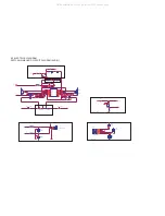
Page 23: ...2N VD7 DTC144 VD7 DTC144 R16 10 R16 10 C15 10U 16V C15 10U 16V VR1 WX10HB 2 20K VR1 WX10HB 2 20K L26 601 L26 601 R10 24K R10 24K XS4 HSJ1594 010060 XS4 HSJ1594 010060 1 2 3 7 4 5 R12 24K R12 24K R19 1 K R19 1 K N20 FMC3 N20 FMC3 1 2 3 4 5 CB1 100n CB1 100n R9 10 K R9 10 K VD18 STZ6 2N VD18 STZ6 2N R18 10 R18 10 N1 LM4863 N1 LM4863 SHUTDOWN 1 GND 2 OUT A 3 VDD 4 OUT A 5 IN A 6 IN A 8 GND 7 IN B 13 ...

Page 24: ... 47uF 16v C107 47uF 16v C90 10U 16V C90 10U 16V CB35 1UF CB35 1UF R64 10K R64 10K C128 22UF C128 22UF C109 100uF 16v C109 100uF 16v CB20 100N CB20 100N R110 10 R110 10 C12 470N C12 470N L28 100 UH L28 100 UH R74 22K R74 22K CB34 1UF CB34 1UF R80 22 R80 22 L18 601H L18 601H CB25 100N CB25 100N CB12 100N CB12 100N R76 22K R76 22K C118 20pF C118 20pF RN3 22 4 RN3 22 4 1 8 2 7 3 6 4 5 CB32 100N CB32 1...

Page 25: ... 2 TP19 TP19 SW3 SW3 1 2 TP18 TP18 TP24 TP24 SW6 SW6 1 2 R03 300 R03 300 1 2 TP21 TP21 SW4 SW4 1 2 C65 1U C65 1U SW5 SW5 1 2 R02 220 R02 220 1 2 R100 10 R100 10 TP22 TP22 D01 MC9S08QG8 D01 MC9S08QG8 RESET 1 PTA4 MS 2 VDD 3 VSS 4 PTA3 13 PTA2 14 PTA1 15 PTA0 16 PTB7 SCL 5 PTB6 SDA 6 PTB2 10 PTB3 9 PTB4 8 PTB5 SS 7 PTB1 11 PTB0 12 R14 33 R14 33 TP25 TP25 TP23 TP23 C6 10UF C6 10UF R05 470 R05 470 1 2...

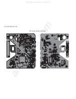
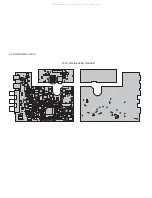
Page 26: ...PET708 MAIN BOARD DIAGRAM 9 0 COMPONENT LAYOUT All manuals and user guides at all guides com a l l g u i d e s c o m ...

Page 27: ...PET708 FUNCTION BOARD DIAGRAM PET708 IF BOARD DIAGRAM PAC130 FUNCTION BOARD DIAGRAM 9 0 COMPONENT LAYOUT All manuals and user guides at all guides com ...

Page 28: ...PAC130 MAIN BOARD DIAGRAM 9 0 COMPONENT LAYOUT All manuals and user guides at all guides com ...

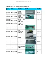
Page 29: ...08 00 PET708 58 PET708 98 996510001129 AY4130 AC POWER ADAPTOR 00 PET708 05 996510001119 AY4130 AC POWER ADAPTOR 05 ACADAPTOR PET708 996510001125 AV OUT CABLE AVCABLE PET708 996510001124 CAR CIGARETTE ADAPTER CARADAPTOR PET708 996510001130 CAR MOUNT AY4246 CARMOUNT PET708 996510001405 PAC131 SECOND SCREEN PAC131 PET708 996510001128 PAC130 POWER CABLE PCABLE PET708 994000003945 RC 810 REMOTE RC All...

Page 30: ... 996510004684 PET708M MAIN PCB ASS Y 58 PET708 98 996510005902 PET708M MAIN PCB ASS Y 98 100 PET708 996510002945 PET708T IF PCB ASS Y 110 PET708 996510002946 PET708K FUNCTION PCB ASS Y 120 PET708 996500038677 FFC 24 PIN LE130 147 PET708 996510002947 24 PIN HARNESS 150 PF 149 PET708 996510001275 LB070W02 TME1 SC TFT LCD 200 PET708 994000004424 KHM 252C LOADING ASS Y 210 PET708 996510002948 YD23 2 S...

Page 31: ...T708 996510002951 DISPLAY FRAME PET708 310 PET708 996510002952 MIDDLE CAB KEY ASS Y PET708 320 PET708 996510002953 BASE COVER PET708 330 PET708 996510002954 ADJUST HINGE PET708 340 PET708 996510002956 DOOR DISCRETENESS PET708 350 PET708 996510002957 DOOR TONGUE PET708 360 PET708 996510002955 DOOR SPRING 410 All manuals and user guides at all guides com a l l g u i d e s c o m ...

Page 32: ...e PET708 75 Version 1 1 3141 785 31661 Add new model and part list for PET708 00 05 58 Version 1 2 3141 785 31662 Update Region Code Change Procedure on section 5 Version 1 3 3141 785 31663 Add partlist for PET708 98 All manuals and user guides at all guides com ...

Reviews: